PAPI 1 style a TILT system

Inactive Publication Date: 2009-09-01
MULTI ELECTRIC MFG CO
View PDF2 Cites 5 Cited by
  • Summary
  • Abstract
  • Description
  • Claims
  • Application Information

AI Technical Summary

Benefits of technology

[0009]Another object of the invention is to provide a PAPI Style

Problems solved by technology

This is necessary since the color of the light seen by the pilot could be erroneous and create a po

Method used


Image

  • PAPI 1 style a TILT system
  • PAPI 1 style a TILT system
  • PAPI 1 style a TILT system

Examples


Embodiment Construction

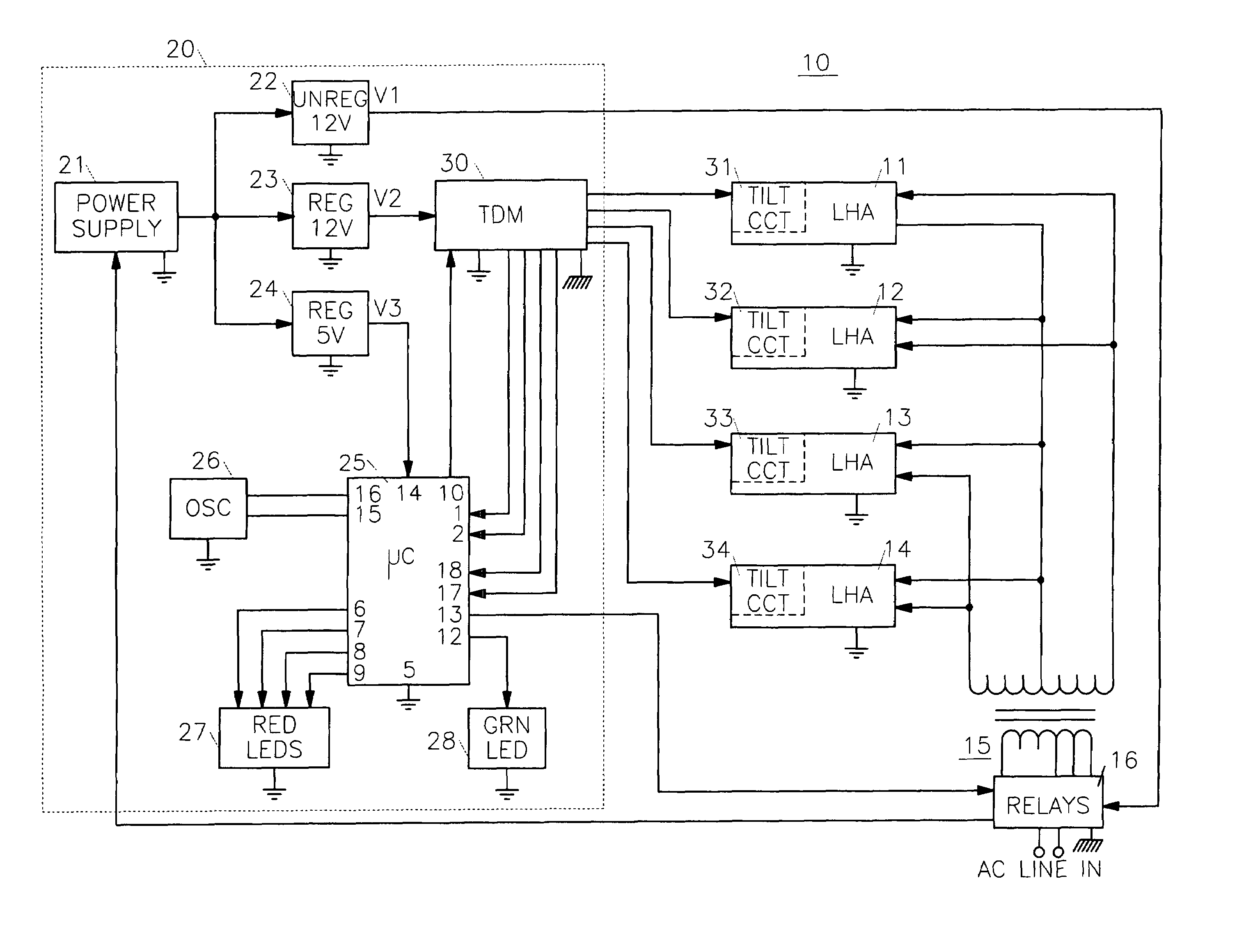
[0016]Referring to FIG. 1, a PAPI Style A system 10, constructed in accordance with the invention, includes four identical LHAs 11, 12, 13, and 14. Each LHA includes a plurality of lamps and suitable lenses (not shown) for displaying either a white light or a red light, depending upon the vertical viewing angle, to an approaching aircraft, as discussed above. A power transformer 15, having a center-tapped secondary winding and a multiple tap primary winding, is connected to a conventional AC source of power through a block 16, labeled Relays. The lamps in the LHAs are powered from the secondary winding of transformer 15 and may have their intensity adjusted, and be turned on and off by operation of one or more relays (not shown) in block 16. Details of these operations are not disclosed as they have no bearing on the present invention.

[0017]A master control, indicated by the components within the dotted-line box 20, includes a DC power supply 21 that is energized from block 16. Powe...


PUM


Abstract

A Style A PAPI system comprises a plurality of identical lamp housing assemblies, each with one or more lamps and each housing assembly including a tilt circuit. A master control includes a microcontroller that supplies an inverted 1 KHz, 50% duty cycle pulse signal to each tilt circuit through a corresponding blocking diode. Each of the tilt circuits includes an optical pendulum tilt switch that responds to tilting of the housing assembly. DC power is developed in each tilt circuit from one phase of the pulse signal. A pair of steering diodes and a voltage divider network enable return pulses to be supplied back to the microcontroller via the same wires that deliver the pulse train. The returned pulses exhibit different voltages corresponding to tilt and no tilt conditions of the tilt switch. Visual indications of the status of each tilt circuit are presented at the tilt circuits and at the master control. The microcontroller disables all of the lamps in the system unless a no tilt voltage is received from every lamp housing assembly.

Description

BACKGROUND OF THE INVENTION AND PRIOR ART[0001]The present invention relates generally to Precision Approach Path Indicator (PAPI) visual guidance systems for aiding pilots in landing an aircraft. Specifically, the PAPI system defines a desired vertical approach angle to a runway and indicates to the pilot, via colored lights, whether the angle of approach of his aircraft to the runway is within the desired approach angle. The colored lights are produced in a number of Lamp Housing Assemblies (LHAs), as will be described below. The Federal Aviation Administration (FAA) establishes the standards for PAPI systems in the United States, whereas the standards for foreign PAPI systems may differ. Therefore it should be understood that, while the present invention is described with respect to the FAA endorsed systems, its application should not be considered as limited to FAA endorsed systems.[0002]The components in an FAA Style B PAPI system are powered by the well-known and widely used c...

Claims


Application Information

Patent Timeline
IPC IPC(8): H05B37/00
CPCH05B37/034H05B47/22
Inventor SANSONE, JOHN M.
Owner MULTI ELECTRIC MFG CO
Why Eureka
Try Eureka