
System for shifting data bits multiple times per clock cycle

a data bit and clock cycle technology, applied in the field of phase rotators, can solve problems such as phase resolution or phase error degraded output characteristics of phase rotators

Inactive Publication Date: 2009-09-01
AVAGO TECH WIRELESS IP SINGAPORE PTE
View PDF11 Cites 0 Cited by
  • Summary
  • Abstract
  • Description
  • Claims
  • Application Information

AI Technical Summary

Benefits of technology

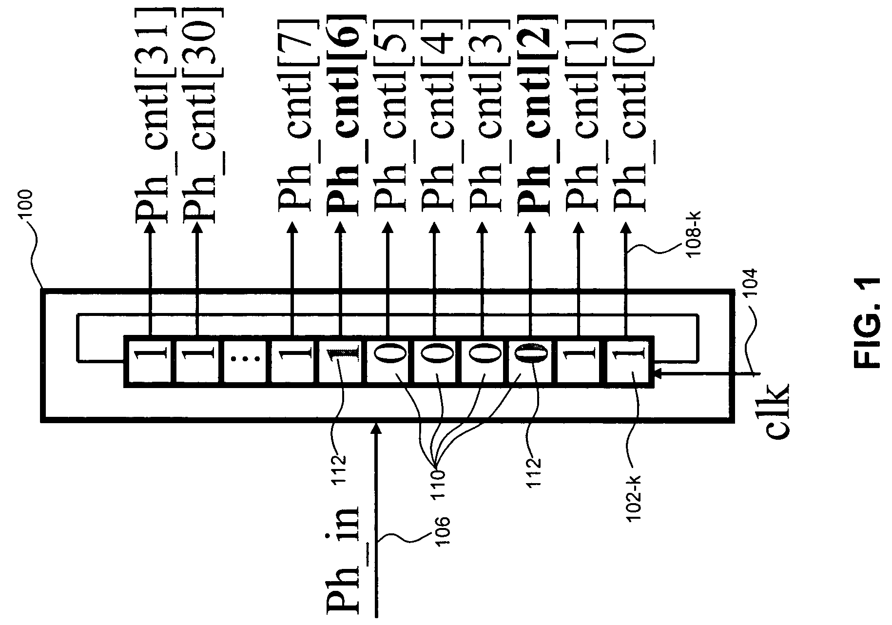
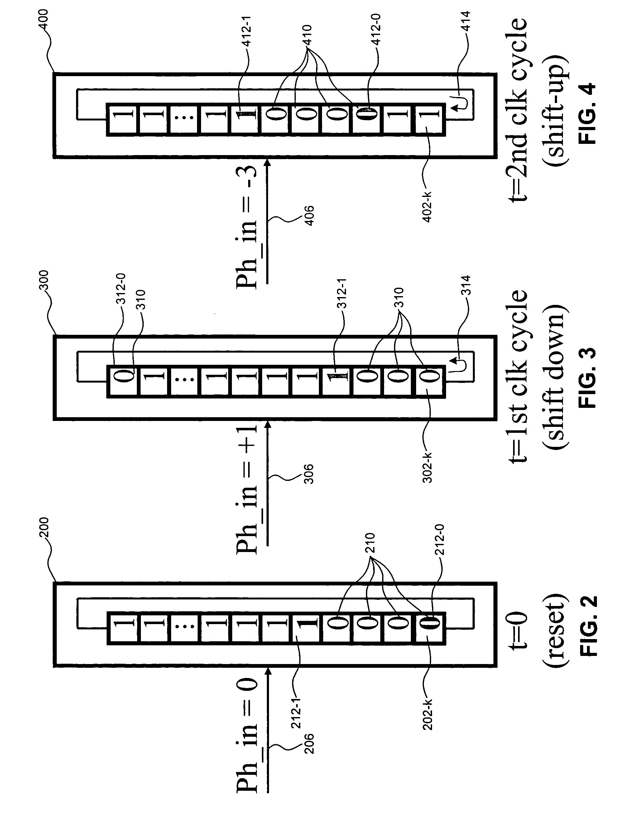
"The present invention provides a system and method for producing phase rotator control signals that can rotate bits in the signals more than one step per clock cycle. This is achieved by controlling the rotation of data bits in a cyclic encoder based on a phase control signal during each clock cycle. By shifting bits multiple times per clock period, the system can maintain desirable phase rotator output characteristics, such as phase resolution or phase error, even when there are more than one bit shift per clock cycle. This allows for improved performance and reliability of the phase rotator."

Problems solved by technology

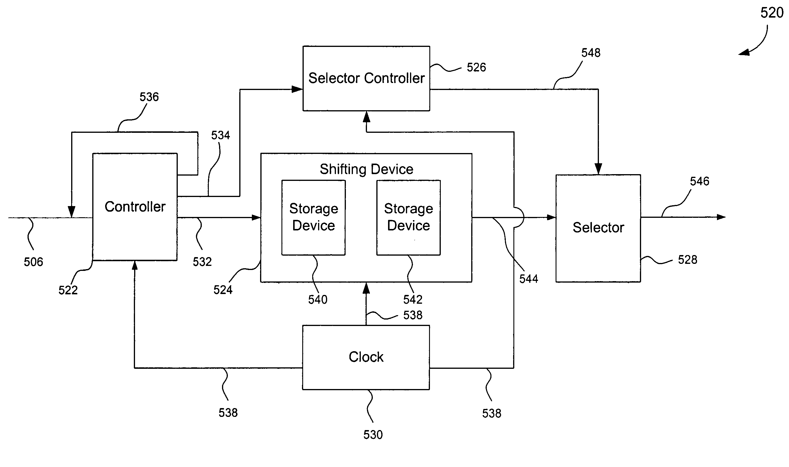
However, when an input phase signal requires more than one bit shift per clock cycle, i.e., rotation step is more than one bit, because the shifting device can only shift once per clock cycle, the phase rotator output characteristics, e.g., phase resolution or phase error, may be degraded.

Method used


Image

  • System for shifting data bits multiple times per clock cycle
  • System for shifting data bits multiple times per clock cycle
  • System for shifting data bits multiple times per clock cycle

Examples


Embodiment Construction

[0018]References in the specification to “one embodiment”, “an embodiment”, “an example embodiment”, etc., indicate that the embodiment described may include a particular feature, structure, or characteristic, but every embodiment may not necessarily include the particular feature, structure, or characteristic. Moreover, such phrases are not necessarily referring to the same embodiment. Further, when a particular feature, structure, or characteristic is described in connection with an embodiment, it is submitted that it is within the knowledge of one skilled in the art to affect such feature, structure, or characteristic in connection with other embodiments whether or not explicitly described.

Overview

[0019]While specific configurations and arrangements are discussed, it should be understood that this is done for illustrative purposes only. A person skilled in the pertinent art will recognize that other configurations and arrangements can be used without departing from the spirit and...


PUM


Abstract

A system and method are used to allow for phase rotator control signals to be produced that rotate bits in the signals more than one step per clock cycle. This can be done through the following operation. First and second data signals that include a plurality of data bits are stored. Rotation of data bits in the first data signal and subsequently data bits in the second data signal is controlled based on a phase control signal during each clock cycle. The first and second controlled data signals are interleaved to form first and second interleaved data signals. One of the first and second interleaved data signals is selected based on a portion of the phase control signal during a second half of the clock cycle. Finally, the selected data signal is transmitted as the phase control signal.

Description

CROSS REFERENCE TO RELATED APPLICATIONS[0001]This application claims benefit under 35 U.S.C. §119(e) to U.S. Provisional Patent Application No. 60 / 665,086, filed Mar. 25, 2005, which is incorporated by reference herein in its entirety.BACKGROUND[0002]1. Field[0003]The present invention relates to phase rotators.[0004]2. Related Art[0005]Presently, a shifting device (e.g., cyclic encoder) is used to adjust bit position in a storage device based on a received phase signal. The shifted bits are then used to form phase control signals for subsequent devices, such as phase rotators. However, when an input phase signal requires more than one bit shift per clock cycle, i.e., rotation step is more than one bit, because the shifting device can only shift once per clock cycle, the phase rotator output characteristics, e.g., phase resolution or phase error, may be degraded.[0006]Therefore, what is needed is a system and method to maintain the desirable phase rotator output characteristics by s...

Claims


Application Information

Patent Timeline
Patent Type & Authority Patents(United States)
IPC IPC(8): H04L7/00
CPCG06F5/015G06F5/017G11C19/00
Inventor PAN, HUILEE, SEONG-HOLE, MICHAEL Q.
Owner AVAGO TECH WIRELESS IP SINGAPORE PTE
Learn More