Method for determining correction values for the measured values of positions of structures on a substrate

a technology of structure position and correction value, which is applied in the direction of speed measurement using gyroscopic effects, average speed measurement, gyroscope/turn-sensitive device, etc., can solve the problem of reducing the throughput of substrates

Active Publication Date: 2009-09-01
VISTEC SEMICON SYST
View PDF14 Cites 5 Cited by
  • Summary
  • Abstract
  • Description
  • Claims
  • Application Information

AI Technical Summary

Benefits of technology

[0018]The rotation of the substrate holder with reference to the coordinate system of the coordinate measuring stage can also be determined. In addition, it is possible to determine a displacement and a rotation of the substrate holder relative to the coordinate system of the coordinate measuring machine.

Problems solved by technology

This is extremely time-consuming and thus reduces the throughput of substrates when the positions of structures on the substrate are measured.

Method used


Image

  • Method for determining correction values for the measured values of positions of structures on a substrate
  • Method for determining correction values for the measured values of positions of structures on a substrate
  • Method for determining correction values for the measured values of positions of structures on a substrate

Examples


Embodiment Construction

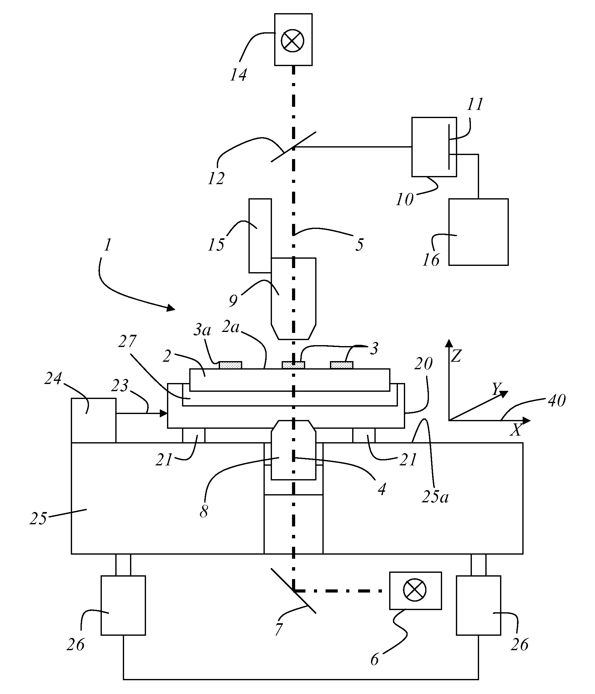
[0031]A coordinate measuring machine 1 of the type described in FIG. 1 is already well known from the prior art. Basically the coordinate measuring machine 1 comprises a plane 25a, in which a measuring stage 20 supported on air bearings is arranged, moveable and traversable in plane 25a. In the embodiment shown here, plane 25a is defined by the X coordinate direction and the Y coordinate direction. Measuring stage 20 is advantageously traversable on air bearings 21 in plane 25a. A substrate holder 27 can be received in measuring stage 20, to support a substrate 2 having a plurality of structures 3 arranged on its surface 2a. The position of measuring stage 20 is detected by at least one laser interferometer 24 which emits a measuring light beam 23. In the embodiment shown here, plane 25a in which measuring stage 20 is moveably arranged is formed by a granite block. It will be understood by a person skilled in the art that this granite block 25 can also be formed of any other materia...


PUM


Abstract

A method for allocating correction values of the degree of bending of a substrate (2) relative to a coordinate system (40) of a coordinate measuring machine (1) is disclosed. The positions of the at least two reference marks (32) on the substrate holder (27) are automatically determined relative to the coordinate system (40) of the coordinate measuring machine (1) for each substrate (2) currently placed in the substrate holder (27) in the coordinate measuring machine (1).

Description

RELATED APPLICATIONS[0001]This application claims priority to German Patent Application No. DE 10 2007 033 619.7, filed on Jul. 17, 2007, which is incorporated herein by reference in its entirety.FIELD OF THE INVENTION[0002]The present invention relates to a method for allocating correction values relating to the bending of a substrate, to the measured values of positions of structures on a substrate relative to the coordinate system of a coordinate measuring machine.BACKGROUND OF THE INVENTION[0003]A measuring device as used for measuring structures on substrates used for the manufacture of wafers (masks) has been disclosed in the paper entitled “Pattern Placement Metrology for Mask Making” by Dr. Carola Bläsing. The paper was held at the Semicon Education Program Convention in Geneva on Mar. 31, 1998. The description given there is the basis for a coordinate measuring machine as used in carrying out the method according to the present invention.[0004]German Patent Application DE 1...

Claims


Application Information

Patent Timeline
Patent Type & Authority Patents(United States)
IPC IPC(8): G01P11/00
CPCG01B21/045
Inventor FRICKE, WOLFGANGGUNDAL, LINDA
Owner VISTEC SEMICON SYST
Why Eureka
Try Eureka