
Feed channel wall for an agricultural harvester

a technology for agricultural harvesters and feed channels, applied in baling, agriculture, agricultural tools and machines, etc., can solve the problems of too complex positioning control of the upstream end region, and achieve the effects of preventing crop jam problems, reducing wear, and preventing friction

Inactive Publication Date: 2009-09-08
DEERE & CO
View PDF6 Cites 27 Cited by
  • Summary
  • Abstract
  • Description
  • Claims
  • Application Information

AI Technical Summary

Benefits of technology

The invention solves the problem of crop blockage in agricultural presses and loader wagons by controlling the position of the feed channel wall using a single control apparatus. This apparatus can be adjusted based on parameters of the feed crop flow or detected with ultrasound or the like and converted into a signal. The use of a spring helps absorb load peaks without immediately resulting in an adjustment of the feed channel wall. The invention is particularly useful in the poorly accessible region between the crop receiver and the crop reservoir.

Problems solved by technology

The problem on which the invention is founded lies in the perception that the positioning control of the upstream end region is too complex.

Method used


Image

  • Feed channel wall for an agricultural harvester
  • Feed channel wall for an agricultural harvester
  • Feed channel wall for an agricultural harvester

Examples


Embodiment Construction

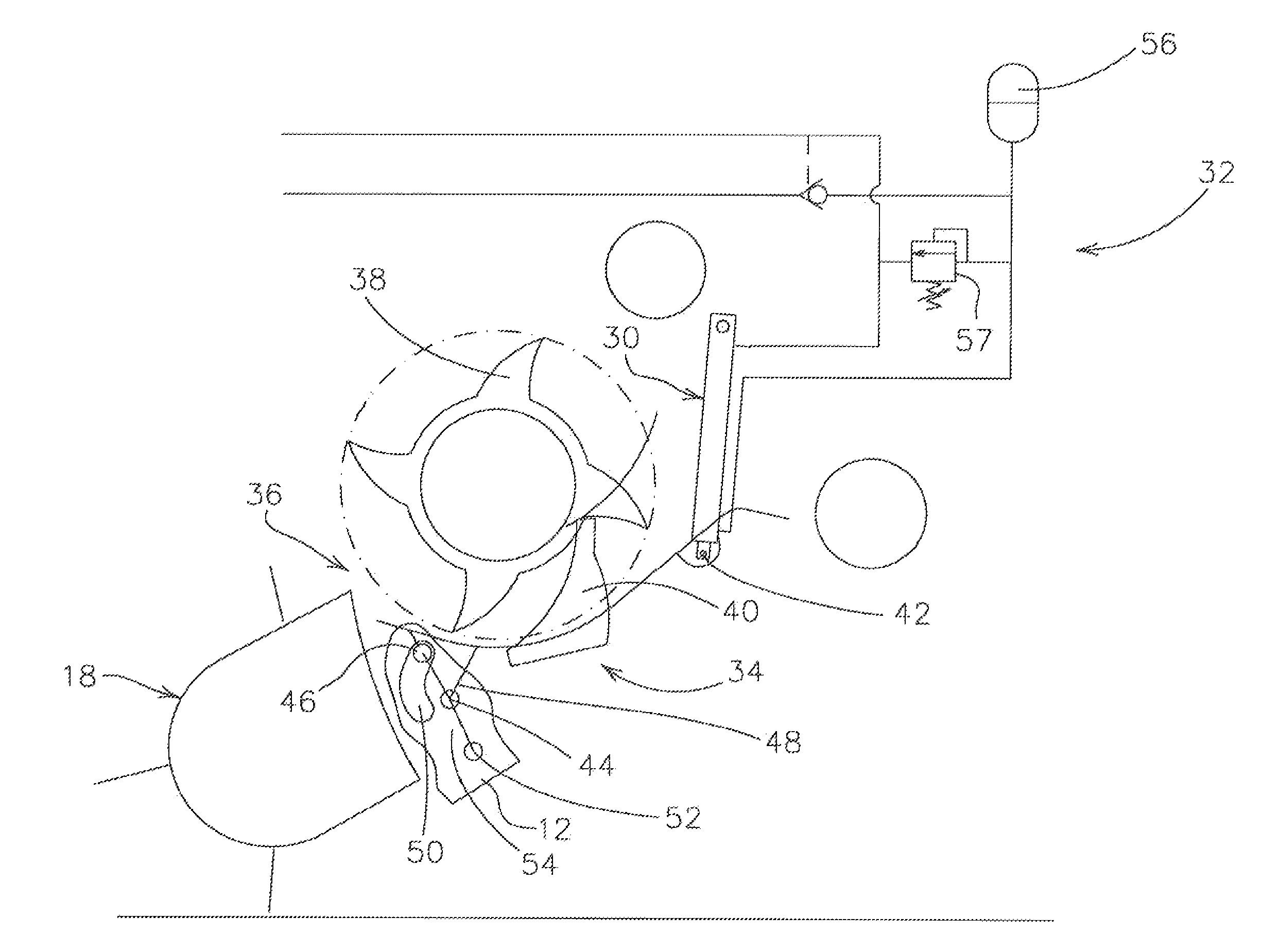
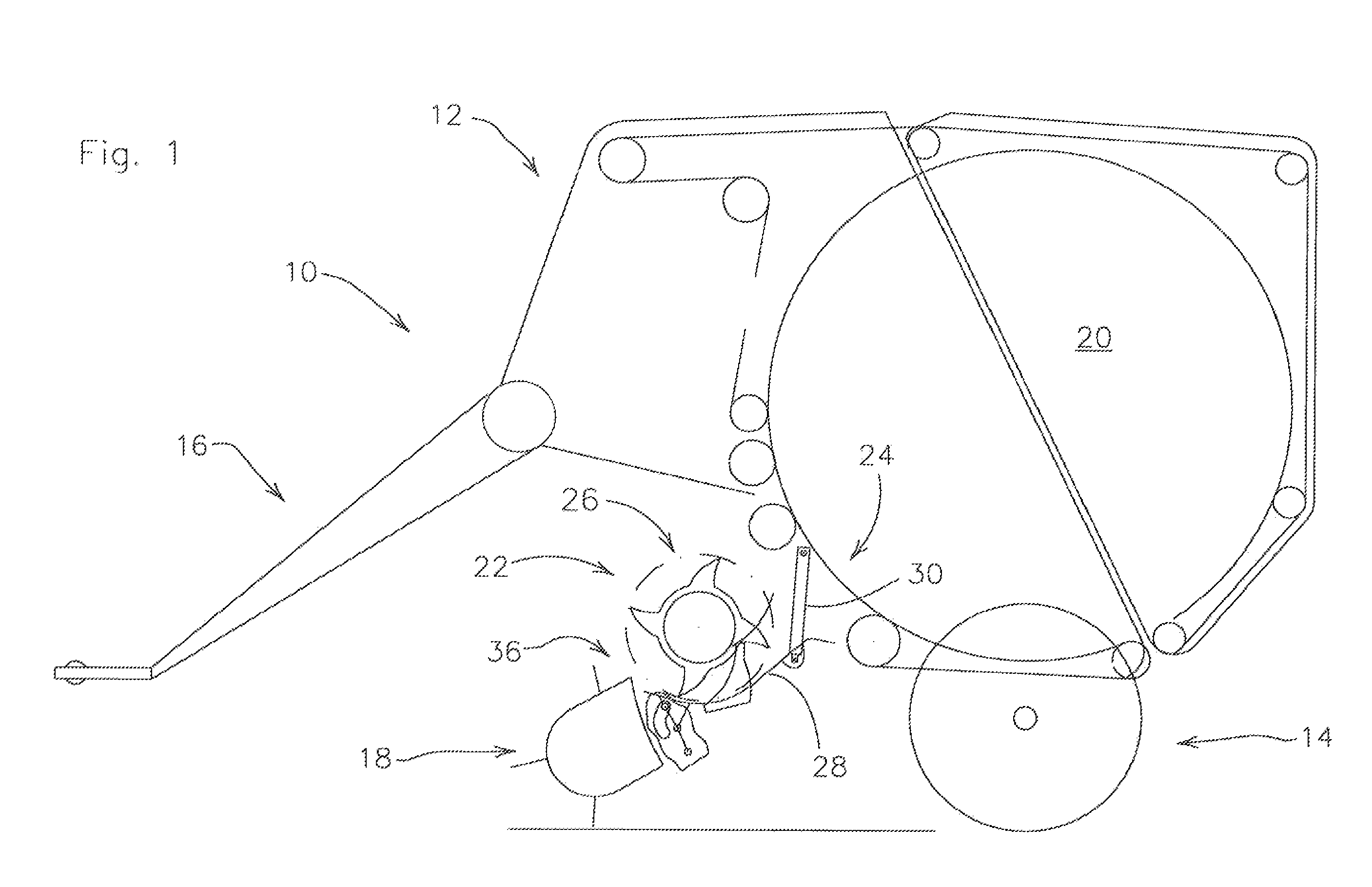
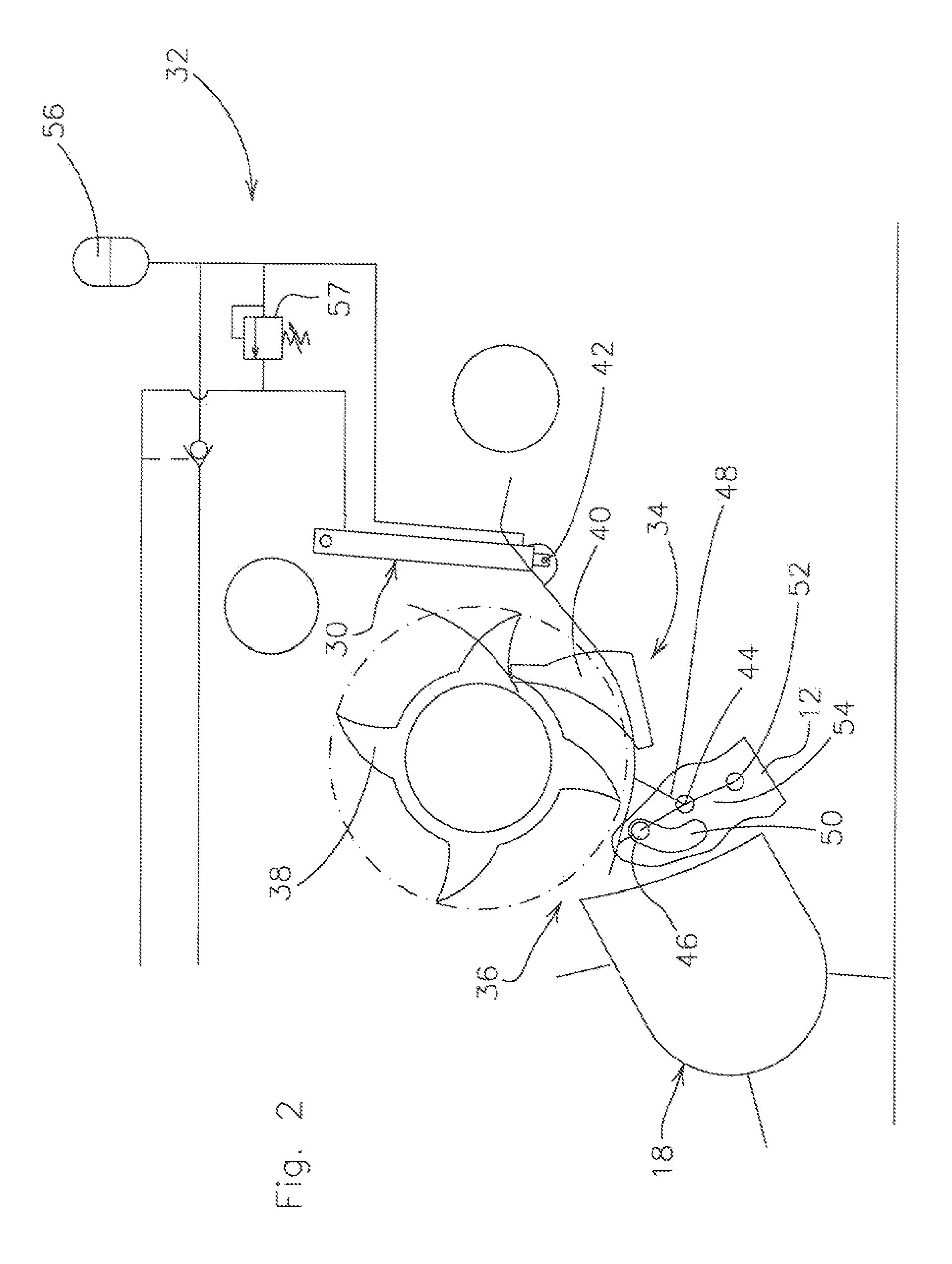
[0018]A press 10, shown in FIG. 1, is of standard construction, i.e., it has a superstructure 12, a chassis 14, a drawbar 16, a crop receiver 18, a crop reservoir 20 and a feed apparatus 22.

[0019]The press 10 is represented as a drawn press 10 having a size-variable crop reservoir 20; it could equally well be a self-propelling press 10 and / or one having a constant-size crop reservoir 20, the type of (non-detailed) press elements being immaterial.

[0020]The superstructure 12 rests on the chassis 14 and bears the crop receiver 18 and the feed apparatus 22 and forms the crop reservoir 20 between (non-detailed) side walls.

[0021]The chassis 14 contains a rigidly or resiliently fitted axle and wheels.

[0022]The drawback 16 is connected in a rigid, or a vertically pivotable, manner to the superstructure 12 and serves for the connection to a towing vehicle (not shown).

[0023]The crop receiver 18 is also referred to as a pick-up and is connected in a vertically movable manner to the superstruct...


PUM


Abstract

A press is provided with a feed channel, whose feed channel wall, in the event of overload, can be pivoted away from a feed rotor. The pivotal motion of the feed channel wall is realized about an upstream bearing, which, by means of a link, is itself moved away from the feed rotor in an upright guide. The motion within the guide is derived from the pivot motion of the feed channel wall away from the feed rotor. A hydraulic cylinder, working against a spring defined by an accumulator, is coupled to a downstream end of the channel wall and resists movement of the channel wall away from the feed rotor, but yields under a preselected crop load.

Description

FIELD OF THE INVENTION[0001]The invention relates to a feed channel wall having an upstream bearing and a downstream connector for a control apparatus which, on the other hand, can be attached to a machine, and having a line between the upstream bearing and a machine-side bearing, and further relates to an agricultural harvester.BACKGROUND OF THE INVENTION[0002]DE 198 41 598 A 1 shows a round baler having a cutting apparatus in a feed channel between a pick-up and a pressing chamber. The bottom of the feed channel can be lowered at both ends in order to prevent a clear crop jams. The upstream end is connected to the pick-up by means of links, which are controlled by a hydraulic cylinder.[0003]The problem on which the invention is founded lies in the perception that the positioning control of the upstream end region is too complex.SUMMARY OF THE INVENTION[0004]This problem is solved according to the invention by the teaching of Patent Claim 1, the other patent claims detailing featur...

Claims


Application Information

Patent Timeline
Patent Type & Authority Patents(United States)
IPC IPC(8): A01D89/00A01D43/02
CPCA01F15/106A01F2015/108A01F2015/107
Inventor VIAUD, JEAN
Owner DEERE & CO
Learn More