Method and apparatus for operating an oil flow control valve

a flow control valve and oil flow technology, applied in the direction of machines/engines, output power, couplings, etc., can solve the problems of difficult implementation of check valves, significant cost to the cylinder head or engine block, and the ocv is manufactured highly facilitated, cost reduction, and improved maintenance conditions

Inactive Publication Date: 2009-09-08
DELPHI TECH INC
View PDF3 Cites 16 Cited by
  • Summary
  • Abstract
  • Description
  • Claims
  • Application Information

AI Technical Summary

Benefits of technology

[0008]An advantage of the invention is that the spool functions as a check valve. Accordingly, a check valve, which was introduced into an OCV according to recent approaches for preventing reverse flow, is no longer necessary. With the check valve having been made redundant, manufacture of the OCV is highly facilitated, resulting in cost reduction and improved maintenance conditions.
[0009]In accord with the present invention, a measure indicative of said oil pressure characteristics on the output side of the oil flow control valve, which preferably is provided by a sensor disposed on or associated with the cam shaft (cam shaft sensor), is accounted for when applying the control method. Relying on sensor data, indicating pressure conditions which could result in reverse flow, allows for reliable synchronisation of the spool movement and the relevant pressure conditions.
[0010]Preferably, the invention provides for a movement of the OCV spool, which involves an oscillation of the spool between a first and an intermediate location or a second location and said intermediate location of the spool, wherein said first location is provided for commanding the cam shaft to an advanced position and wherein said second location is provided for commanding the cam shaft to a retarded position. During oscillation the spool periodically opens and closes the oil ports in antiphase with the oil pressure characteristics on the output side of the OCV, i.e. the ports are blocked at high pressure and the ports are open at low pressure conditions.
[0011]Furthermore preferably, said oscillation is effected by means of synchronous energisation or de-energisation of a control unit provided for positioning the spool. More particularly, said energisation or de-energisation involves energisation or de-energisation of a coil disposed in the control unit. Displacement and movement of the spool is then induced by means relying on electromagnetic effects, which allows for almost instantaneous response to the relevant control signals since the oscillation, i.e. the movement of the spool, can be very fast.
[0012]In further accord with the present invention, synchronously displacing the spool with combustion demands and synchronously moving the spool with oil pressure characteristics is effected by overlaying a first energisation or de-energisation signal for said coil derived on account of said combustion demands and a second energisation or de-energisation signal for said coil derived on account of said pressure characteristics.
[0013]The invention also pertains to an apparatus for controlling the oil flow control valve in a combustion engine according to the above mentioned or subsequently described method steps. To this end the apparatus comprises means provided for and capable of performing these method steps, such as at least one sensor, more particularly the abovementioned cam shaft sensor, means for evaluating readings from said sensor, and means for affecting the OCV, more particularly the spool comprised in the OCV, on account of such evaluation.

Problems solved by technology

This can lead to a certain amount of reverse oil flow across the OCV, diminishing the phase rate performance of the cam phasing system.
However, this approach adds significant cost to the cylinder head or engine block.
Also, the implementation of the check valve can be difficult because of oil routing.

Method used


Image

  • Method and apparatus for operating an oil flow control valve
  • Method and apparatus for operating an oil flow control valve
  • Method and apparatus for operating an oil flow control valve

Examples


Embodiment Construction

[0022]In the following description, for purposes of explanation and not limitation, specific details are set forth, such as particular embodiments, data flows, signalling implementations, interfaces, techniques, etc. in order to provide a thorough understanding of the present invention. However, detailed descriptions of well-known methods, interfaces, devices, and signalling techniques are omitted so as not to obscure the description of the present invention with unnecessary detail. Moreover, individual function blocks are shown in some of the figures. Those skilled in the art will appreciate that the functions may be implemented using individual hardware circuits, using software functioning in conjunction with a suitably programmed digital microprocessor or general purpose computer, such as an application specific integrated circuit (ASIC).

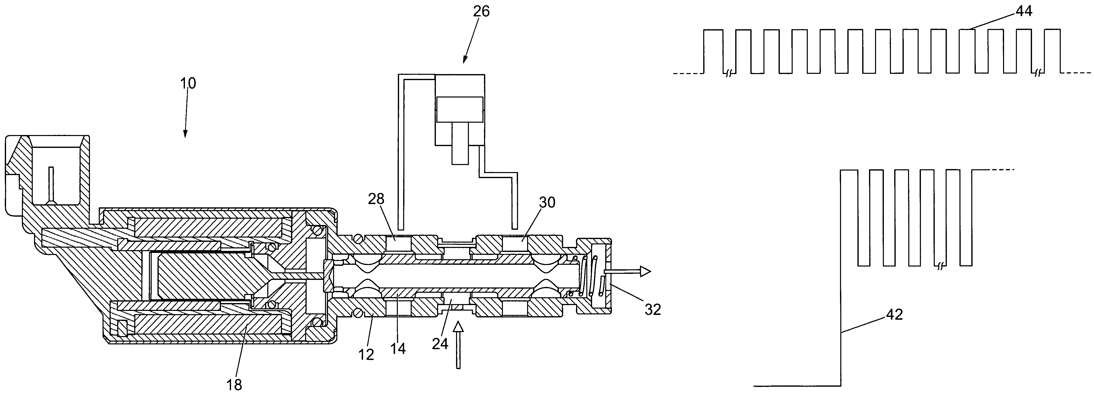
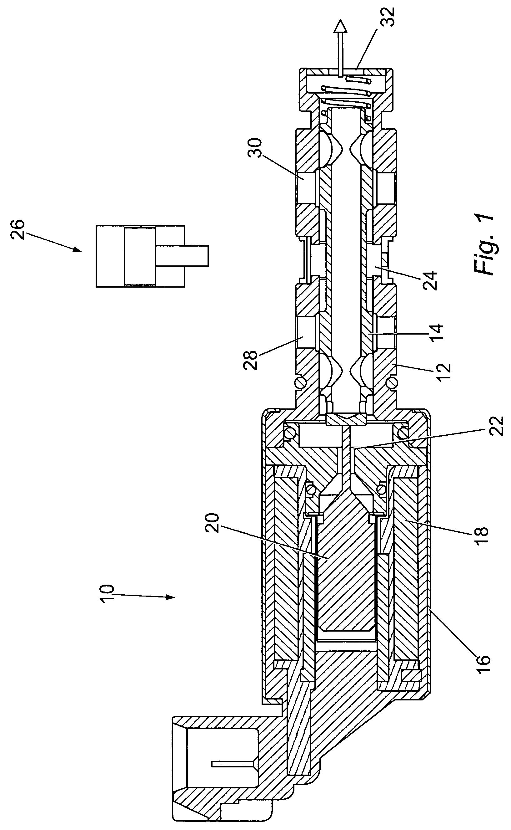
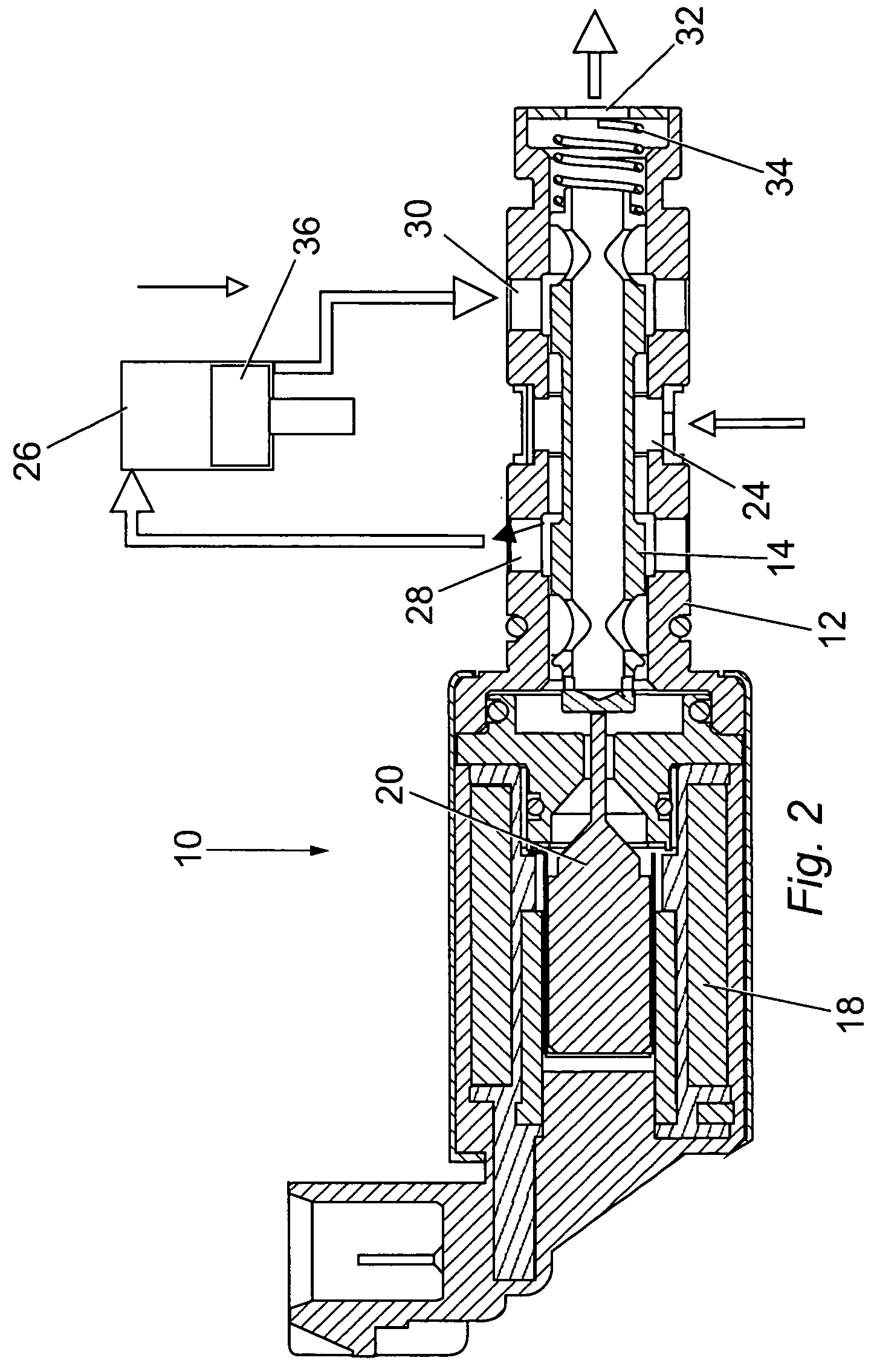
[0023]FIG. 1 shows a sectional view of an oil flow control valve (OCV) 10. The OCV 10 comprises a housing 12, a spool 14 located in the housing ...


PUM


Abstract

An oil flow control valve (10) in a combustion engine is operated for affecting a cam phaser (26) disposed at an output side of said oil flow control valve (10). The cam phaser includes a spool (14) disposed in a spool housing (12). The method for operating the valve includes synchronising a displacement of said spool (14) in said housing (12) with combustion demands, and synchronising movement of said spool (14) with oil pressure characteristics on the output side of the oil flow control valve (10).

Description

FIELD OF THE INVENTION[0001]The present invention generally relates to an oil flow control valve for a cam phaser. The invention more particularly relates to a method and a corresponding apparatus for operating and / or controlling said oil flow control valve.BACKGROUND OF THE INVENTION[0002]Cam phasers, as is known in the art, are used to control the angular relationship of a pulley or sprocket to a camshaft of a combustion engine. A variable cam phaser (VCP) allows changing the phase relationship while the engine is running. Typically, a VCP is used to shift an intake cam on a dual overhead cam engine in order to broaden the torque curve of the engine, to increase peak power at high revolution speeds, and to improve the idle quality. Also, an exhaust cam can be shifted by a cam phaser in order to provide internal charge diluent control, which can significantly reduce HC and NOx emissions, or to improve fuel economy. The above objectives are in the following briefly termed as combust...

Claims


Application Information

Patent Timeline
Patent Type & Authority Patents(United States)
IPC IPC(8): F01L1/34
CPCF01L1/34F01L1/3442F02D13/0253F01L2001/3443F01L2001/34426Y10T137/86574Y10T137/86622Y10T137/8671
Inventor BERNDORFER, AXEL H.
Owner DELPHI TECH INC
Why Eureka
Try Eureka