Boring tool

a technology of boring tool and drive mechanism, which is applied in the direction of drilling tools, boring/drilling apparatus, reaming tools, etc., can solve the problems of comparatively large overall length of the drive mechanism provided here for converting the rotary movement of the setting member into a displacement of the bit holder, and the construction of this boring tool is comparatively complicated. , to achieve the effect of low cost, small play and high transmission ratio

Active Publication Date: 2009-09-08
HEINZ KAISER
View PDF23 Cites 9 Cited by
  • Summary
  • Abstract
  • Description
  • Claims
  • Application Information

AI Technical Summary

Benefits of technology

[0006]In the boring tool of the generic type, the drive mechanism can be realized with few individual parts and in a compact type of construction and very cost-effectively. Due to a corresponding difference in the thread pitches, the differential spindle permits a very high transmission ratio while at the same time permitting small play. In the boring tool according to the invention, a scale is thus possible on the setting member, in which scale the distance between two scale lines corresponds to a displacement movement of one μm.
[0007]According to a development of the invention, provision is made for the differential spindle to be mounted in a bore of the tool carrier. In this case, an especially short type of construction is possible when the bore and thus the differential spindle run transversely to the rotation axis of the tool carrier. The comparatively short type of construction results in high stability.
[0008]According to a development of the invention, provision is made for the setting member to have a graduated dial which is arranged laterally on the tool body. This permits a simple and accurate setting, for example by means of hexagon key.

Problems solved by technology

However, the drive mechanism provided here for converting the rotary movement of the setting member into a displacement of the bit holder requires a comparatively large overall length.
In addition, the construction of this boring tool is comparatively complicated.

Method used


Image

  • Boring tool
  • Boring tool
  • Boring tool

Examples


Embodiment Construction

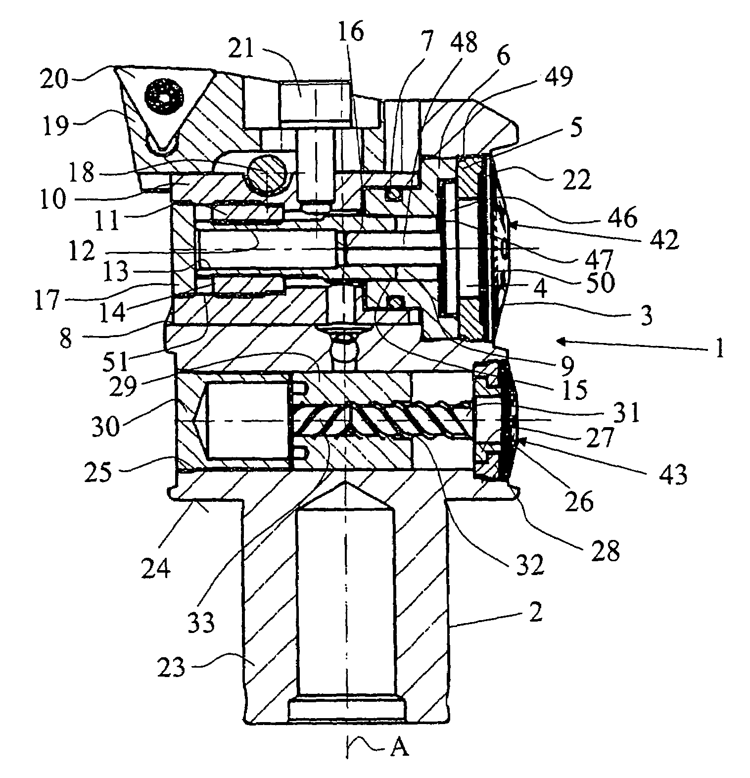
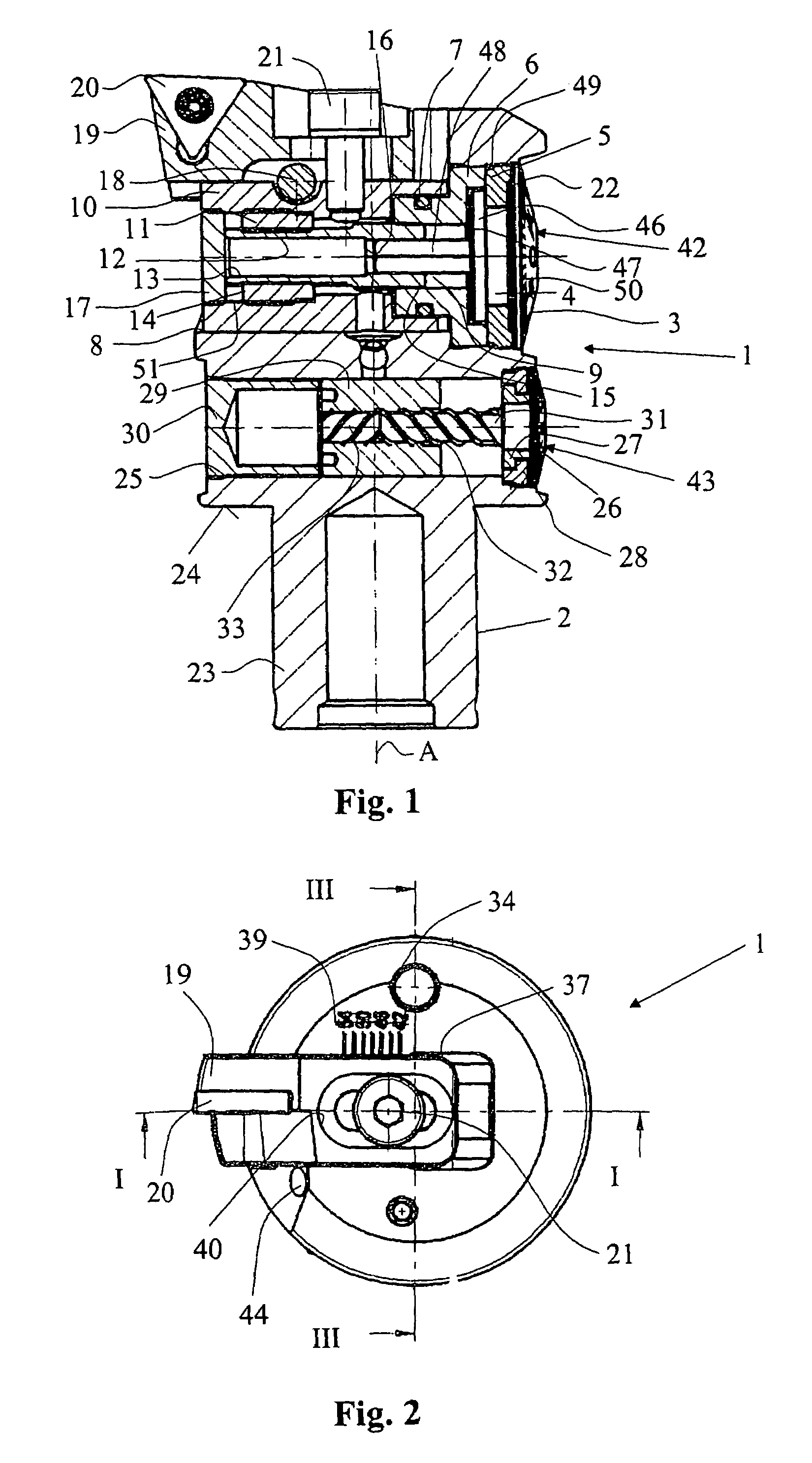
[0018]FIG. 1 shows a boring head 1 which has a tool body 2 which has a radial bore 8, in which a tool carrier 10 is mounted in such a way as to be radially displaceable to a limited extent. As can be seen, the bore 8 is a continuous stepped bore. At a distance from the bore 8, the tool body 2 has a further bore 25, which runs parallel to the bore 8 and in which a balancing weight 29 can be displaced by means of a spindle 31 for compensating for unbalance. Both bores 8 and 25 run at right angles to the rotation axis A of the boring head 1. In addition, the tool body 2 has a shank 23, with which the boring head 1 can be connected to a shank (not shown here) or the like, a surface 24 being pressed against this shank or the like by means of at least one clamping screw (not shown here).

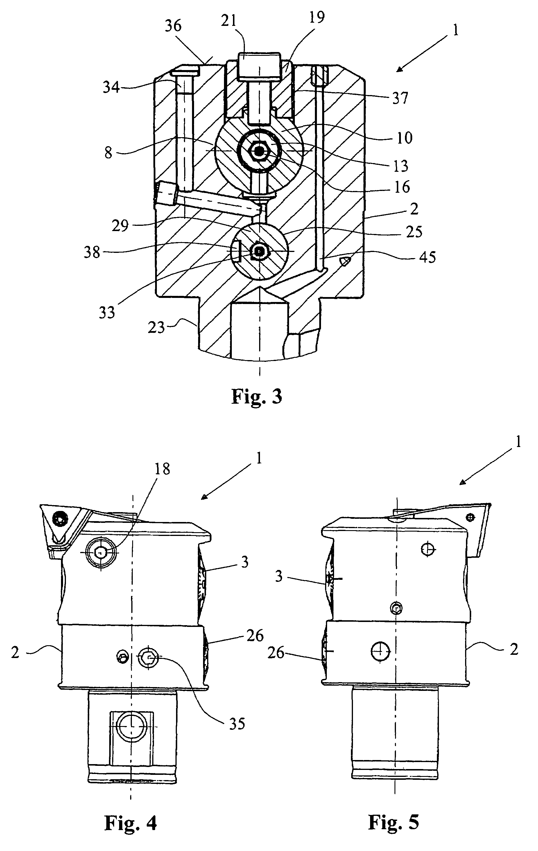
[0019]According to FIG. 3, the tool carrier 10 is arranged below a groove 37, which is incorporated in the end face 36 of the tool body 2 and in which an indexable-insert holder 19 is mounted in such a way...


PUM

PropertyMeasurementUnit
distanceaaaaaaaaaa
diameteraaaaaaaaaa
bore diameteraaaaaaaaaa

Abstract

The boring tool has a tool body (2) on which a tool carrier (10) is mounted in a radially adjustable manner. A setting member (42) serves to set the boring diameter. A drive mechanism converts a rotation of the setting member (42) into a displacement of the tool carrier (10). The drive mechanism has a differential spindle (13) which converts a rotation of a graduated disk (26) into a displacement of the tool carrier (10) for the fine setting of the boring diameter. The differential spindle (13) is mounted in a bore (51) of the tool carrier (10) and extends at right angles to the rotation axis (A).

Description

SUMMARY OF THE INVENTION[0001]The invention relates to a boring tool having a tool body on which a tool carrier is mounted in an adjustable manner, having a rotatable setting member with which the tool carrier is radially displaceable via a drive mechanism for setting the boring diameter, the drive mechanism converting a rotation of the setting member into a displacement of the tool carrier.[0002]Boring tools have been known for a long time. They serve, for example, in particular for the finish machining of precision bores. On the tool body, the tool as a rule is an indexable-insert holder which is releasably mounted on the tool carrier for the coarse setting. The drive mechanism serves for the fine setting of the outside diameter with the range of a few μm or micrometers.[0003]A boring tool of said type has been disclosed by DE-A-43 32 520. In the axial direction, this boring tool has a cylindrical bore in which an adjusting screw having a fine-pitch thread is mounted. This adjusti...

Claims


Application Information

Patent Timeline
Patent Type & Authority Patents(United States)
IPC IPC(8): B23B29/03
CPCB23B29/03407B23B2250/04B23B2260/056B23B2260/088Y10T408/8598Y10T408/85995Y10T408/885Y10T408/6764Y10T408/65B23B29/03B23B29/034
Inventor STADELMANN, RUDOLFSTADELMANN, RALPHHANGGI, ERNST
Owner HEINZ KAISER
Why Eureka
Try Eureka