Method and system for regulation of the rotational speed of a rotor on a wind turbine

a technology of rotating speed and wind turbine, which is applied in the direction of electric generator control, machines/engines, mechanical equipment, etc., can solve the problems of reducing the degree of aerodynamic efficiency of blades, and reducing the efficiency of wind turbines, so as to achieve the effect of increasing energy outpu

Active Publication Date: 2009-09-08
SIEMENS GAMESA RENEWABLE ENERGY SERVICE GMBH
View PDF23 Cites 40 Cited by
  • Summary
  • Abstract
  • Description
  • Claims
  • Application Information

AI Technical Summary

Benefits of technology

[0012]The object of the invention is to further develop a method and a system for the regulation of the rotational speed of a rotor of a wind turbine with a generator and a rotor blade such that a higher energy output is possible.
[0023]The third rotational speed target value is preferably determined from a torque actual value. The regulation method is particularly efficient when the third rotational speed target value, in particular with, in particular a specifiable, time delay, tracks the torque actual value. A particularly efficient gust identification is thereby possible and an efficient utilization or even a readjustment of the wind turbine at gusts to the optimum operating point is possible, whereby high power efficiency is given.
[0025]It is particularly preferred if in the case of the exceeding of an, in particular specifiable, difference of a rotational speed actual value from the first, second and / or third rotational speed target value and / or in the case of the exceeding of an, in particular specifiable, value of the torque difference, the wind turbine is braked or the speed of the rotor is quickly reduced. In the case of the exceeding of the regulation deviation of the torque or the rotor speed from a deviation limit value, the system then detects an error. For example, the torque falls to 0 when the generator fails. In this case, the torque regulation deviation increases very strongly. The regulator then changes its regulation algorithm since the system then brakes or must be stopped. In this case, the blade angle target value is, for example, intensified or maximized namely in the direction of a lower rate of revolution. An important advantage of this regulation method is that the method or the regulator itself detects an error and can react quicker.
[0028]The first and / or the second rotational speed target value are preferably changeable or variable rotational speed target values. The first rotational speed target value determination device and the second rotational speed target value determination device are preferably one single device. In this case, the device can have several outputs. If a third device is provided for the determination of a third rotational speed target value (third rotational speed target value determination device), wherein one output of the third rotational speed target value determination device is connected with one input of the first and / or second rotational speed target value determination device, the efficiency of the wind turbine, in particular in the case of gusts, can be increased very well. Within the framework of the invention, connected is understood as an, in particular indirect, connection for example via a cable or a data bus. A wireless data connection or another type of connection can also be provided. All rotational speed target value determination devices are preferably provided in one single device and / or in one common housing. Advantageously, the first, second and / or third device is at least a data processing device or at least a computer or comprises at least one computer.

Problems solved by technology

Thus, the degree of aerodynamic efficiency of the blades worsens in that they are driven out of their optimal adjustment angle.
The transition between partial and full load mode is not handled or is only insufficiently handled.
This partially results in considerable profit cuts.

Method used


Image

  • Method and system for regulation of the rotational speed of a rotor on a wind turbine
  • Method and system for regulation of the rotational speed of a rotor on a wind turbine
  • Method and system for regulation of the rotational speed of a rotor on a wind turbine

Examples


Embodiment Construction

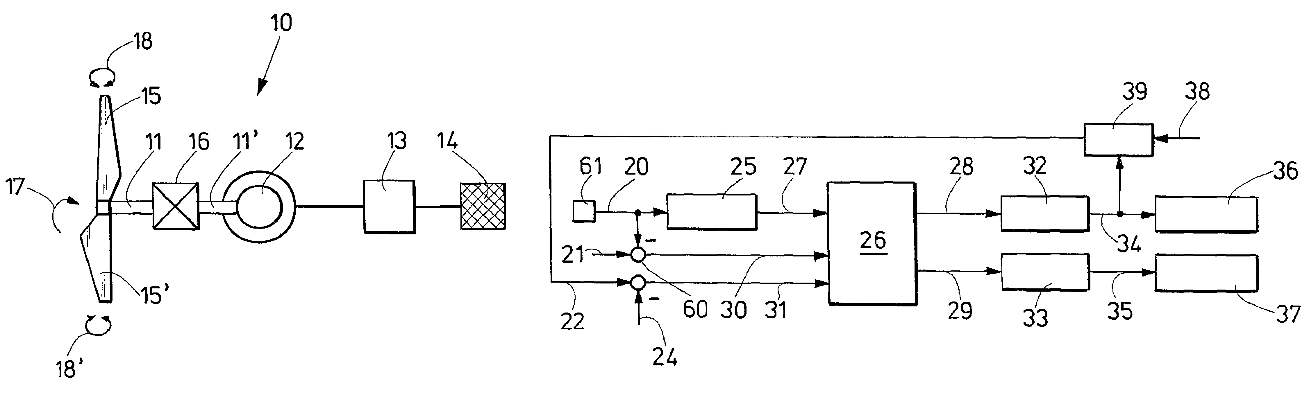
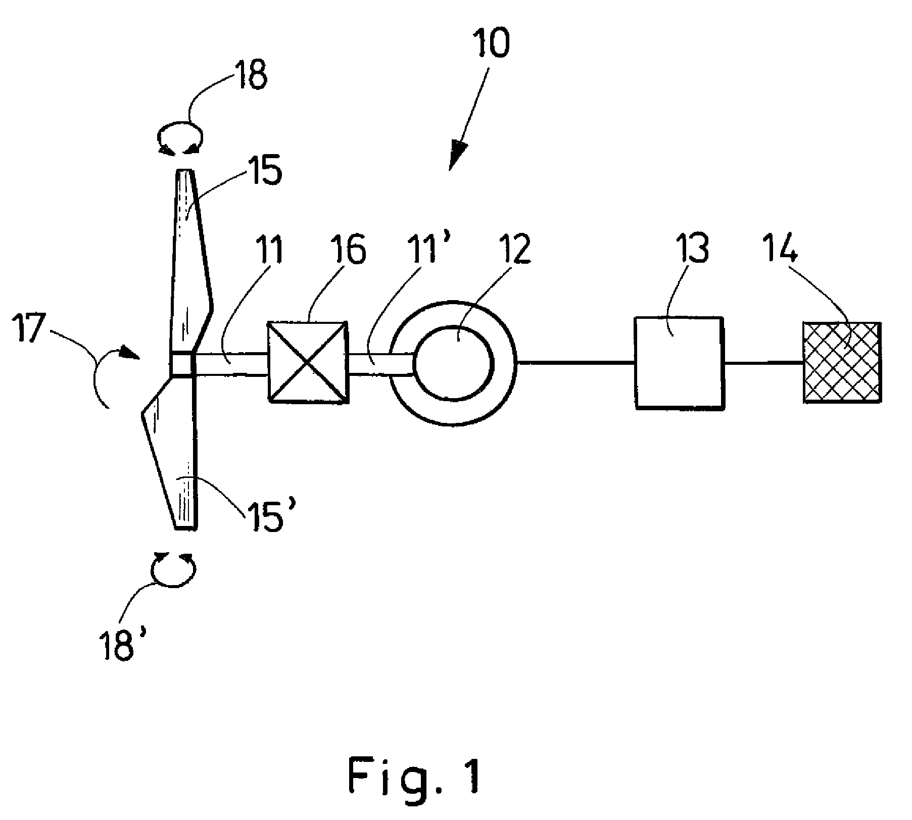
[0037]FIG. 1 shows in a very schematic manner a wind turbine 10, comprising a rotor 11, on which rotor blades 15 and 15′ are arranged. The rotor 11 is connected with a drive 16. The drive 16 is connected with a generator 12 via a shaft 11′. The rotor 11 is rotatable, namely according to an indicated rotational direction 17. Through corresponding rotation of the rotor 11 and via the drive 16 also of the shaft 11′, a conventional generator 12, for example, an asynchronous generator, can create electrical power, which can be made available to a network or grid 14, to which the consumers are for example connected, via a converter 13. Accordingly, convention regulations of rotational speed-variably operated systems are described for example in the book by Siegfried Heier, “Windkraftanlagen, Systemauslegung, Netzintegration und Regelung,” (Wind Turbines, System Design, Network Integration and Regulation) Verlag Teubner, 2005, pages 320 through 328. FIG. 1 also indicates the change in the ...


PUM


Abstract

The invention relates to a method and a system for regulation of the rotational speed (52) of a rotor on a wind energy unit with a generator and a rotor blade. The first set parameter is a pitch angle (Pitch) of the rotor blade and the second set parameter is the torque of the generator. The system comprises a pitch angle control or regulation device (32), a torque control or regulation device (33), a first device for determination of a first rotational speed set value (28) (first rotational speed set value determination device (29)) and a second device (26) for determination of a second rotational speed set value (29) (second rotational speed set value determination device (26)). The first rotational speed set value (28) may be supplied to the pitch angle control or regulation device (32) and the second rotational speed set value (29) may be supplied to the torque control or regulation device (33), wherein the first and second rotational speed set value (28, 2)) may be different from each other.

Description

[0001]This application is a continuation of currently pending PCT application PCT / EP2006 / 005794, filed on Jun. 16, 2006, the entire disclosure of which is incorporated by reference herein.BACKGROUND OF THE INVENTION[0002]The invention relates to a method and a system for the regulation of the rotational speed of a rotor of a wind turbine (wind energy plant), wherein the wind turbine comprises a generator and a rotor blade.[0003]A wind energy plant or wind turbine converts wind energy into electrical energy and feeds it mostly into a public power supply system. This occurs when the kinetic energy of the wind displaces the rotor into a rotational movement, which is forwarded to a generator and is converted into an electrical current.[0004]Different approaches are selected for the regulation of the rotational speed of a rotor of a speed-variable wind turbine. Two operating states are normally differentiated, namely the speed regulation in partial load mode and in full load mode, wherei...

Claims


Application Information

Patent Timeline
Patent Type & Authority Patents(United States)
IPC IPC(8): F03D9/00H02P9/04
CPCF03D7/0276F03D7/042F03D9/003H02P9/04H02P9/305F05B2270/101F05B2270/1032H02P2101/15Y02E10/723Y02E10/725F05B2270/20F03D9/255F03D9/25Y02E10/72
Inventor KRUEGER, THOMAS
Owner SIEMENS GAMESA RENEWABLE ENERGY SERVICE GMBH
Why Eureka
Try Eureka