Manufacturing method of secondary battery, restraining jig for secondary battery, charging/discharging device for secondary battery, and charging device for secondary battery

a secondary battery and charging device technology, applied in the direction of secondary battery servicing/maintenance, cell components, sustainable manufacturing/processing, etc., can solve the problems of deteriorating secondary battery productivity, battery case leakage, etc., and achieve the effect of reducing the cost of a manufacturing facility and quick charging/discharging

Active Publication Date: 2009-09-08
TOYOTA JIDOSHA KK
View PDF3 Cites 11 Cited by
  • Summary
  • Abstract
  • Description
  • Claims
  • Application Information

AI Technical Summary

Benefits of technology

[0008]The present invention has been made in view of the above circumstances and has an object to overcome the above problems and to provide a manufacturing method of a secondary battery, a restraining jig for a secondary battery, a charging / discharging device for a secondary battery, and a charging device for a secondary battery that can swiftly perform a charging / discharging process and provide satisfactory productivity of a secondary battery.

Problems solved by technology

Therefore, there is a possibility of distortion or deformation produced on the battery can (battery case).
Further, the electrolytic solution might be leaked due to the breakdown at the joint section (welding section) of the battery can (battery case).
As described above, the technique in the publication '526 brings a troublesome and time-consuming operation before the start of the charging / discharging and after the end thereof (including the waiting time until the expansion of the battery case is stopped), thereby entailing a problem of deteriorating productivity of the secondary battery.

Method used


Image

  • Manufacturing method of secondary battery, restraining jig for secondary battery, charging/discharging device for secondary battery, and charging device for secondary battery
  • Manufacturing method of secondary battery, restraining jig for secondary battery, charging/discharging device for secondary battery, and charging device for secondary battery
  • Manufacturing method of secondary battery, restraining jig for secondary battery, charging/discharging device for secondary battery, and charging device for secondary battery

Examples


Embodiment Construction

[0094]A detailed description of a preferred embodiment of the present invention will now be given referring to the accompanying drawings.

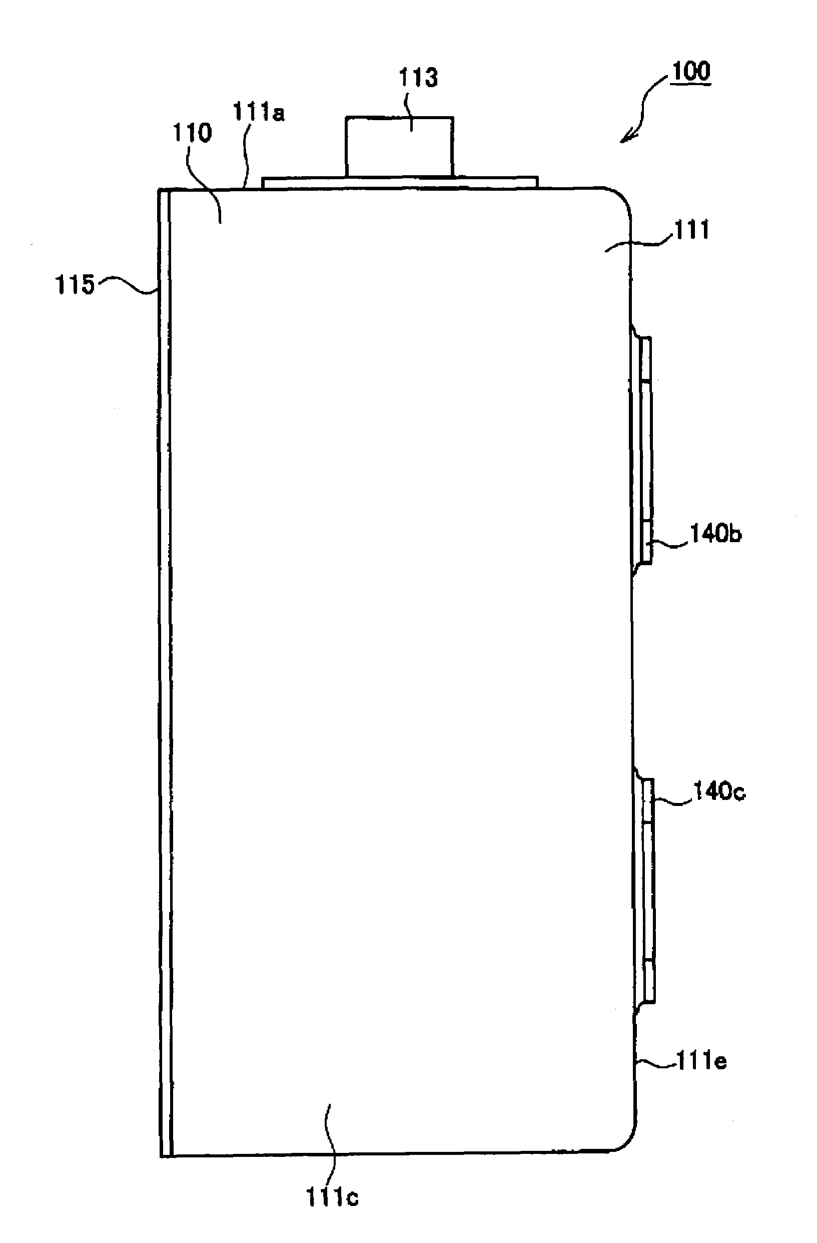
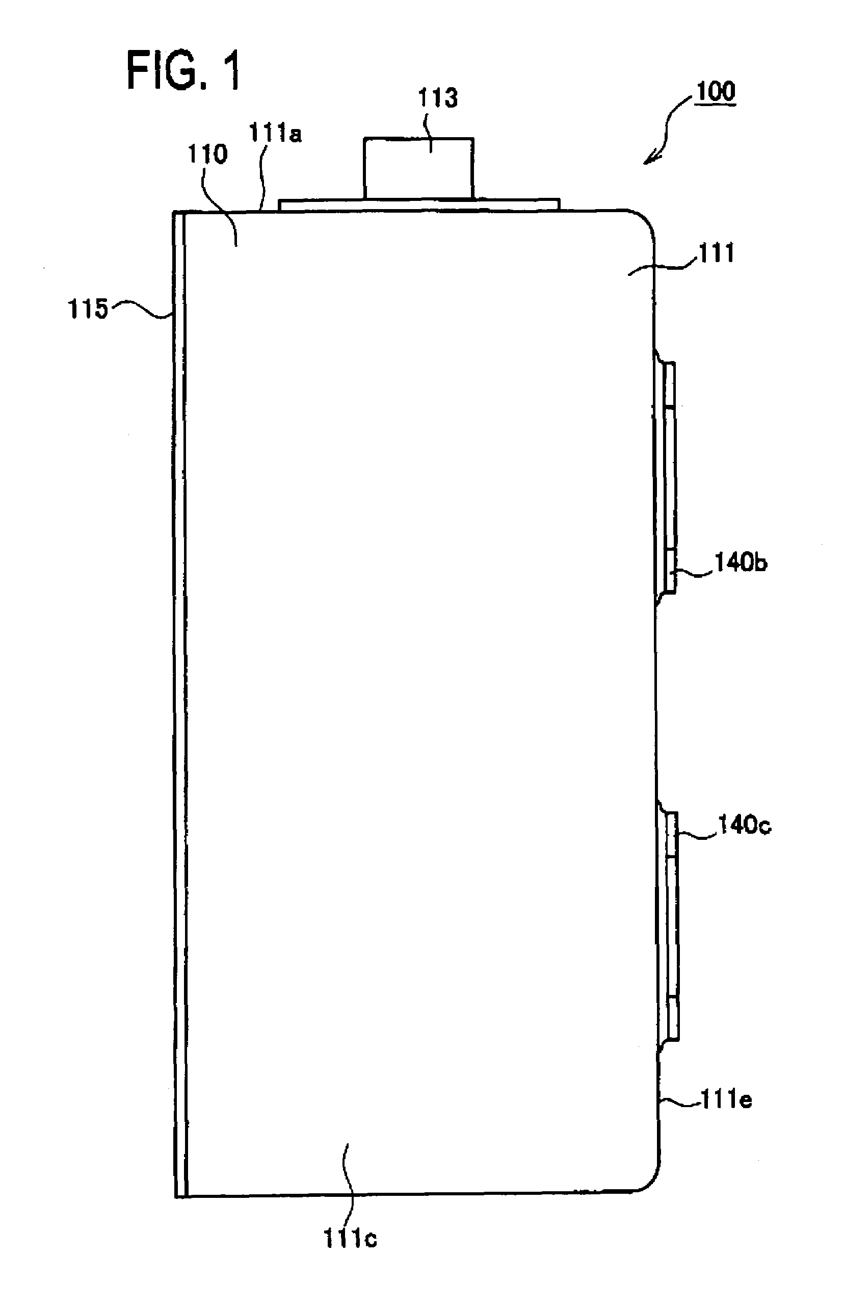
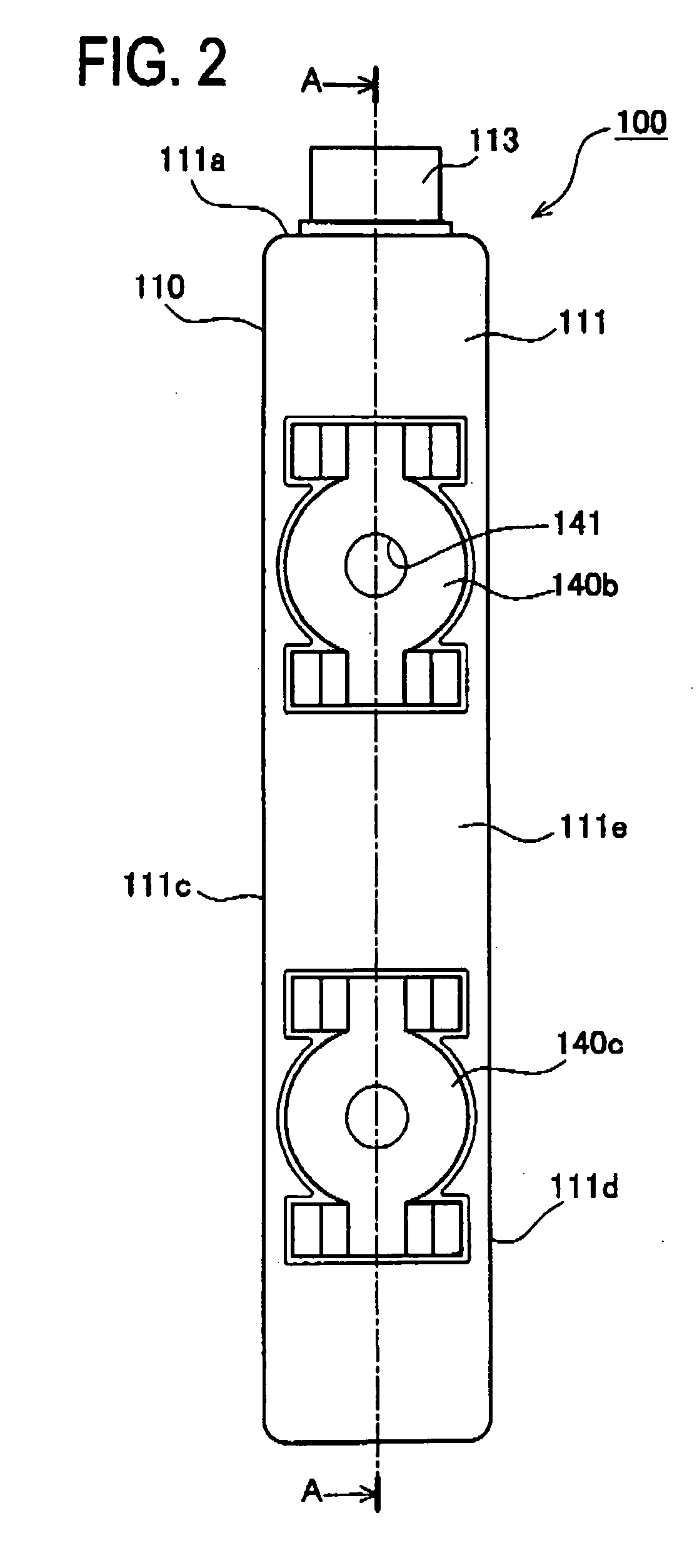
[0095]FIG. 1 is a front view of a secondary battery 100 according to the embodiment, FIG. 2 is a side view thereof, and FIG. 3 is a sectional view thereof (corresponding to the sectional view taken along a line A-A in FIG. 2).

[0096]The secondary battery 100 according to this embodiment is a rectangular closed nickel hydride storage battery provided with a metallic (specifically, nickel plating steel plate) battery case 110, a safety valve device 113, and a pole plate group 120 (see FIG. 3) and electrolytic solution (not shown) arranged in the battery case 110. In this embodiment, the pole plate group 120 and electrolytic solution correspond to a power generating element.

[0097]The pole plate group 120 is configured such that, as shown in FIG. 3, plural positive plates 121 having positive electrode active material layer 121s and plural negative plate...


PUM

PropertyMeasurementUnit
specific gravityaaaaaaaaaa
voltageaaaaaaaaaa
temperatureaaaaaaaaaa

Abstract

A manufacturing method of a secondary battery according to the present invention includes a charging / discharging process wherein the secondary battery is arranged to a restraining jig, that restricts an expansion caused on the battery case with respect to at least a part of the battery case and that is configured to be removable from a charging / discharging device with the secondary battery arranged thereto regardless of the magnitude of the internal pressure in the secondary battery; a charging / discharging is performed to the secondary battery with the restraining jig mounted to the charging / discharging device; and after the completion of the charging / discharging, the restraining jig is removed from the charging / discharging device with the secondary battery arranged to the restraining jig.

Description

BACKGROUND OF THE INVENTION[0001]1. Field of the Invention[0002]The present invention relates to a manufacturing method of a secondary battery, a restraining jig for a secondary battery, a charging / discharging device for a secondary battery, and a charging device for a secondary battery.[0003]2. Description of Related Arts[0004]Recently, a demand for a secondary battery such as nickel hydride battery, lithium ion battery, or the like has been increased with the development of mobile equipment such as cellular phone, portable personal computer, or the like or practicalization of pure electric vehicle or hybrid electric vehicle. During the manufacturing process of a secondary battery, each component is assembled, and then, a battery is activated by performing a charging / discharging to necessarily adjust the characteristic of each battery to a predetermined characteristic. Various types have been proposed for a charging / discharging method after the assembly of the battery and a chargin...

Claims


Application Information

Patent Timeline
Patent Type & Authority Patents(United States)
IPC IPC(8): H02J7/00H01M50/202H01M50/204H01M50/296
CPCH01M2/1016H01M10/04H01M10/46H01M10/44Y10T29/49108Y02E60/124Y02E60/10Y02P70/50H01M50/204H01M50/202H01M50/296
Inventor ONISHI, MASATOTANAKA, YASUFUMIITO, KOJIRO
Owner TOYOTA JIDOSHA KK
Why Eureka
Try Eureka