High frequency ultrasound detection using polymer optical-ring resonator

a polymer optical ring and high frequency ultrasound technology, applied in the field of ultrasonic detection, can solve the problems of reduced element size, device inability to show early stages of atherosclerosis, signal noise increases with reduced element size, etc., to achieve the effect of increasing detection noise, signal noise increasing, and reducing element siz

Active Publication Date: 2009-09-08
RGT UNIV OF MICHIGAN
View PDF2 Cites 11 Cited by
  • Summary
  • Abstract
  • Description
  • Claims
  • Application Information

AI Technical Summary

Benefits of technology

[0006]Very high frequency ultrasound imaging at the frequency range of 30-100 MHz is capable of resolving structures almost down to the cellular level. Developing such an imaging modality for clinical use could have a tremendous impact on the diagnostic and therapeutic procedures in many different clinical areas. The cardio-vascular clinician will be able to visualize in great detail the arterial walls of the coronary arteries and the heart interior structure. The diagnostics of cancer using biopsy will be revolutionized as in-situ microscopy could replace the traditional procedure. Imaging guided therapy could be developed since the diagnosed pathology can be localized at a great precision.
[0008]According to the principles of the present teachings, a method is provided that is based on optical microresonators of very high quality factor acting as highly sensitive ultrasound receivers. These microresonators, designed using integrated optics techniques, are formed using closed-loop (ring type) shaped waveguides. A typical dimension of such a microresonator is 20 μm to 60 μm depending on the optical wavelength and other design parameters. Preliminary measurements showed an extraordinary high sensitivity giving rise to a high signal to noise ratio of about 30 using a driving acoustic signal of 60 KPa power. These experiments were performed using a microring resonator of moderate quality factor (Q=1000) excited using relatively low optical power of 1.5 mW. These results imply that a microring array having an element spacing of less than 20 μm could deliver high sensitivity and provide image resolution that is at least five times better that of any existing IVUS system. Such a system can utilize separate optical elements acting as ultrasound generators whose principle relying on photoacoustic ultrasound generation.
[0009]The design of a 1-D or 2-D microring array using integrated optics device techniques according to the present teachings offers unique advantages such as ruggedness, small size, RF immunity, and low manufacturing cost, which could be beneficial in various ultrasound applications. A particularly appealing medical application is the design of a small integrated optical device which will operate as an intravascular imaging probe. The ultrasound pulse generator could be integrated using photoacoustic methods, therefore eliminating the need for any electrical cabling since fiber optics carry both input and output signals. The high element density required for high resolution intravascular imaging dictates an upper limit on the ring diameter. Reducing the size of the rings will also increase the free spectral range and therefore will increase the number of elements that can share a common bus waveguide.

Problems solved by technology

For the case of a piezoelectric sensing element, however, signal noise increases with reduced element size.
Due to their limited resolution current IVUS devices are unable to show early stages of atherosclerosis, or to identify thin fibrous caps, a hallmark of plaques believed to be most susceptible to rupture.

Method used


Image

  • High frequency ultrasound detection using polymer optical-ring resonator
  • High frequency ultrasound detection using polymer optical-ring resonator
  • High frequency ultrasound detection using polymer optical-ring resonator

Examples


Embodiment Construction

[0033]The following description of the preferred embodiments are merely exemplary in nature and is in no way intended to limit the present teachings, its application, or uses.

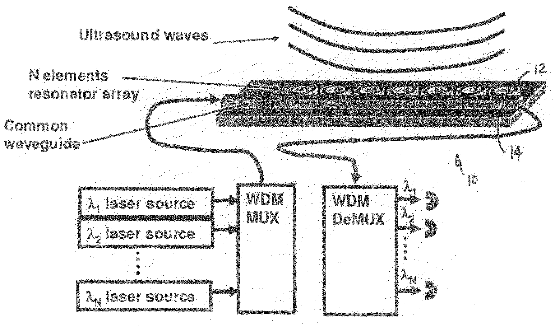
[0034]The present teachings are believed to boost optical detection of ultrasound from the current experimental system carried out on an optical table to a compact and robust device that is perfectly suitable for interventional imaging application. The integrated optics concept and the novel implementation of photonic microresonators as ultrasonic detectors are the corner stones of the present teachings.

[0035]From a medical perspective, the greatest impact of the present teachings would be on the treatment of cardio-vascular diseases. A device based on the present teachings can feature one or more of the following:[0036]1. High-resolution imaging revealing detailed structures such as the thin fibrous cap covering vulnerable plaque.[0037]2. High image contrast obtained by realizing several imaging modalities on ...


PUM


Abstract

A polymer waveguide resonator device for high-frequency ultrasound detection having a optical resonator coupled to a straight optical waveguide which serves as input and output ports. Acoustic waves irradiating the waveguide induce strain modifying the waveguide cross-section or other design property. As a consequence, the effective refractive index of optical waves propagating along the ring is modified. The sharp wavelength dependence of the high Q-factor resonator enhances the optical response to acoustic strain. High sensitivity is demonstrated experimentally in detecting broadband ultrasound pulses from a 10 MHz transducer.

Description

CROSS-REFERENCE TO RELATED APPLICATIONS[0001]This application claims the benefit of U.S. Provisional Application No. 60 / 607,982, filed on Sep. 8, 2004. The disclosure of the above application is incorporated herein by reference.GOVERNMENT RIGHTS[0002]This invention was made with government support under Grant Nos. HL47401 and EB007619 awarded by the National Institutes of Health. The government has certain rights in the invention.FIELD[0003]The present teachings relate to ultrasound detection and, more particularly, relate to high frequency ultrasound detection using polymer optical-ring resonators.BACKGROUND AND SUMMARY[0004]Detection of ultrasound using optical techniques has gained increasing interest during recent years. Resonant optical structures, such as etalons, fiber gratings, and dielectric multilayer interference filters, can be employed as ultrasound sensing elements. These devices rely on the interaction of an optical field confined in a resonance cavity with a transien...

Claims


Application Information

Patent Timeline
Patent Type & Authority Patents(United States)
IPC IPC(8): G02B6/00
CPCA61B5/0097G02B6/1221G02B6/12007G01H9/004G02B6/138
Inventor ASHKENAZI, SHAIGUO, LINGJIE JAYO'DONNELL, MATTHEW
Owner RGT UNIV OF MICHIGAN
Why Eureka
Try Eureka