Woodworking machine

a woodworking machine and handwheel technology, applied in the field of woodworking machines, can solve the problems of unfavorable direct transmission of the rotary movement of the handwheel to the swivel frame, unfavorable operation, safety risk, etc., and achieve the effects of enhancing operation convenience and accuracy, high reduction ratio, and high reduction ratio

Inactive Publication Date: 2009-09-15
SCHWEPPACH FAB VON HOLZBEARBEITUNGSMASCHINEN GMBH
View PDF26 Cites 7 Cited by
  • Summary
  • Abstract
  • Description
  • Claims
  • Application Information

AI Technical Summary

Benefits of technology

[0006]In this example, the table board as well as the swivel frame together with the tool bracket constitute a group of components all of which, in an advantageous manner, can be pre-assembled. This fact ensures an exact position of the swivel axis of the swivel frame, which is coplanar with the table surface, and thus a high degree of obtainable working accuracy. The adjusting rod associated with the swivel frame and actuatable by means of an actuating means further ensures a high reduction ratio which has an advantageous effect on the achievable degree of operating accuracy. The same applies to the articulated shaft associated with the tool bracket, ahead of and / or following which provision may be made for reduction devices. A further advantage of the measures according to the invention lies in the fact that each actuating means, due to its flexibility within the drive train, is in a stationary position relative to the swivel frame and / or the tool bracket, so that neither in this case a reach-through slot in the housing associated with a shaft connected with an actuating means is required. As a result, a high degree of user-friendliness and safety as well as high stability of the machine housing is obtained. The measures according to the invention thus in an advantageous manner completely avoid the disadvantages of the prior art arrangement.
[0008]Thus, the adjusting rod associated with the swivel frame may advantageously be designed as a threaded spindle which on one side engages a bolt which is swivel-mounted in the swivel frame and in axial direction accommodated stationary in the same, and is on the other side swivel-mounted about the axle of the associated actuating means and acts together with the associated actuating means via angle drive. By using a threaded spindle, a comparatively high reduction ratio is achieved which, if required, may even be increased by a suitable design of the angle drive. Furthermore, the threaded spindle in an advantageous manner causes a self-locking effect which enhances operating convenience and accuracy.
[0009]In a further development, the adjustin element associated with the tool bracket may advantageously be designed as a threaded spindle which is provided on the swivel frame in a vertical position, which threaded spindle engages a bolt firmly attached to the tool bracket and, via an angle drive, is connected with an articulated shaft provided with joints at both ends thereof. This arrangement likewise ensures in an advantageous manner a high reduction ratio as well as a self-locking effect.
[0011]Expediently, the swivel frame may be designed as a casting comprising a vertical wall which is provided with at least one window opening toward the top through which passes a shaft carrying a cutting tool and, on the side away from the tool comprises a projection accommodating the vertical threaded spindle associated with the tool bracket, as well as guiding means for the tool bracket in a direction parallel to the spindle. This arrangement permits a low-cost and torsion-resistant design of the swivel frame. It is therefore sufficient to provide one adjusting rod.
[0012]Advantageously, the swivel frame, at least on its tool side, may be provided with a circumferential marginal flange to which a cover plate is attached and which is preferably interrupted in the tool area. Thus, a chamber associated with the tool and opening towards the top is advantageously formed which can be connected to an exhaust device, which facilitates chip removal.
[0013]Expediently, the tool bracket may likewise be designed as a casting comprising a vertical wall which, on the one hand, is provided with projections having guide sleeves, as well as a bearing region associated with the tool carrying shaft, and, on the other hand, with a projection comprising the nut acting together with the threaded spindle thus forming the adjusting element. This arrangement results in a tool bracket which combines the advantages of low-cost and torsion-resistant construction. Simultaneously, the use of castings for the swivel frame and the tool bracket permit a high degree of freedom from vibration, which likewise has a positive effect on the obtainable degree of accuracy.

Problems solved by technology

The disadvantage, however, of such an arrangement lies in the fact that the pinion shaft carries out all swivel movements of the swivel frame, so that the handwheel accommodated on the pinion shaft changes its position during each swivel movement of the swivel frame.
This constitutes an undesirable effect with regard to operation.
Furthermore, the reach-through slot of the machine frame, through which the pinion shaft extends may constitute a safety risk and has to be guarded accordingly.
The direct transmission of the rotary movement of the handwheel to the swivel frame has an unfavourable effect also with regard to the obtainable degree of accuracy.
Furthermore, in the known arrangement the swivel frame suspended in the machine frame is separated from the table board, rendering assembly difficult.

Method used


Image

  • Woodworking machine
  • Woodworking machine
  • Woodworking machine

Examples


Embodiment Construction

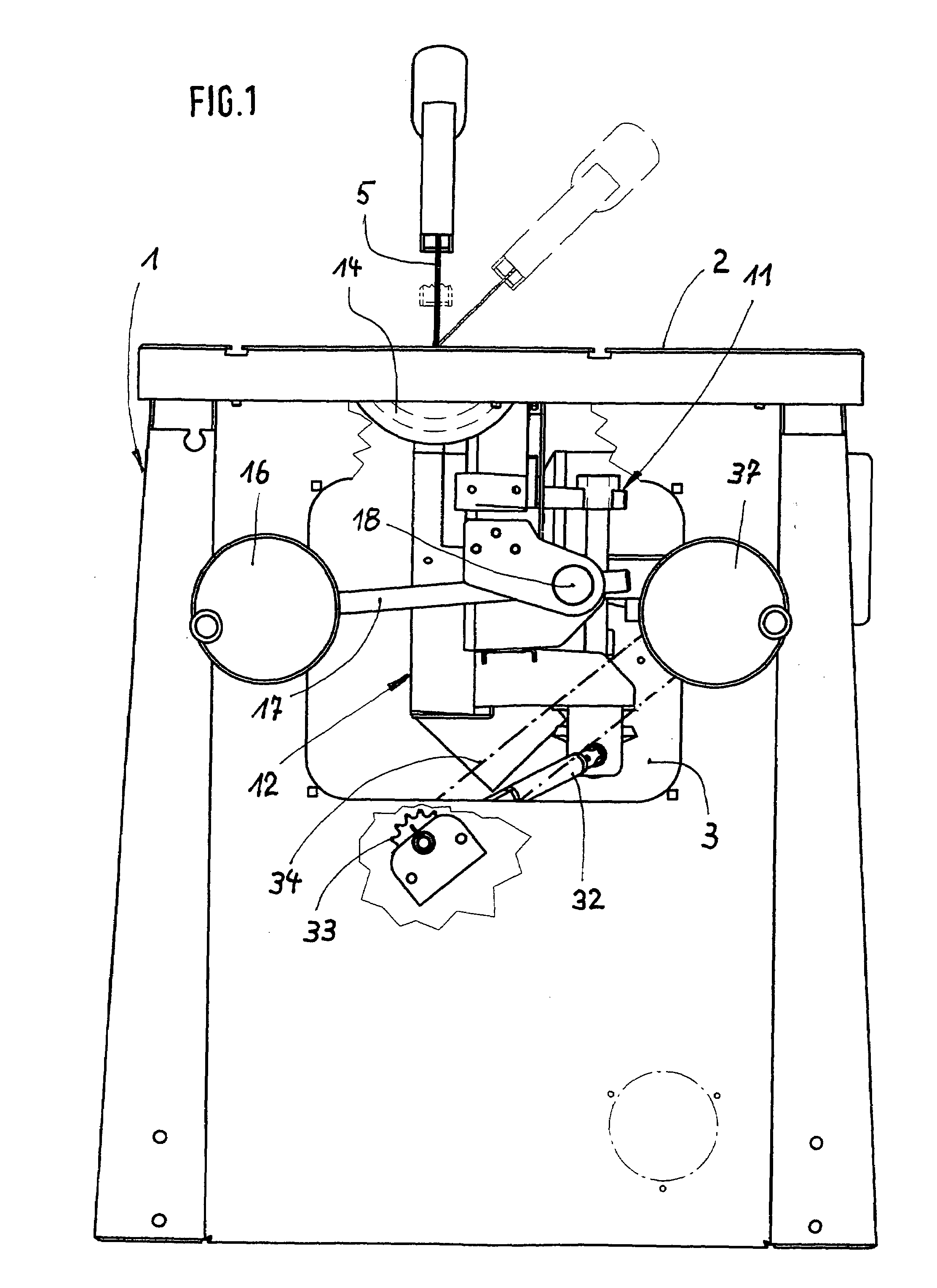
[0015]FIG. 1 shows a view of the operator side of a circular saw according to the invention with removed inspection cover and a partly broken out front wall;

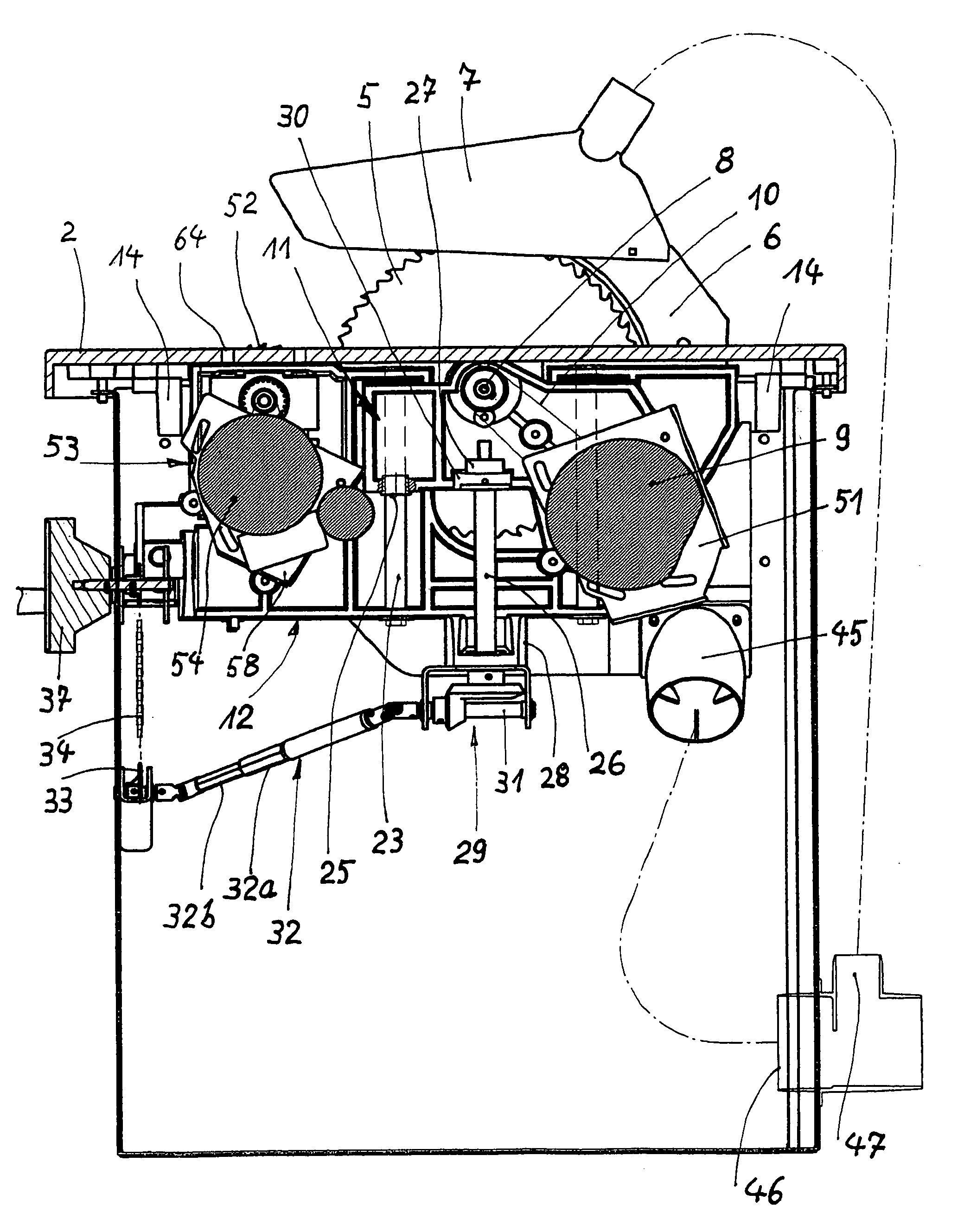
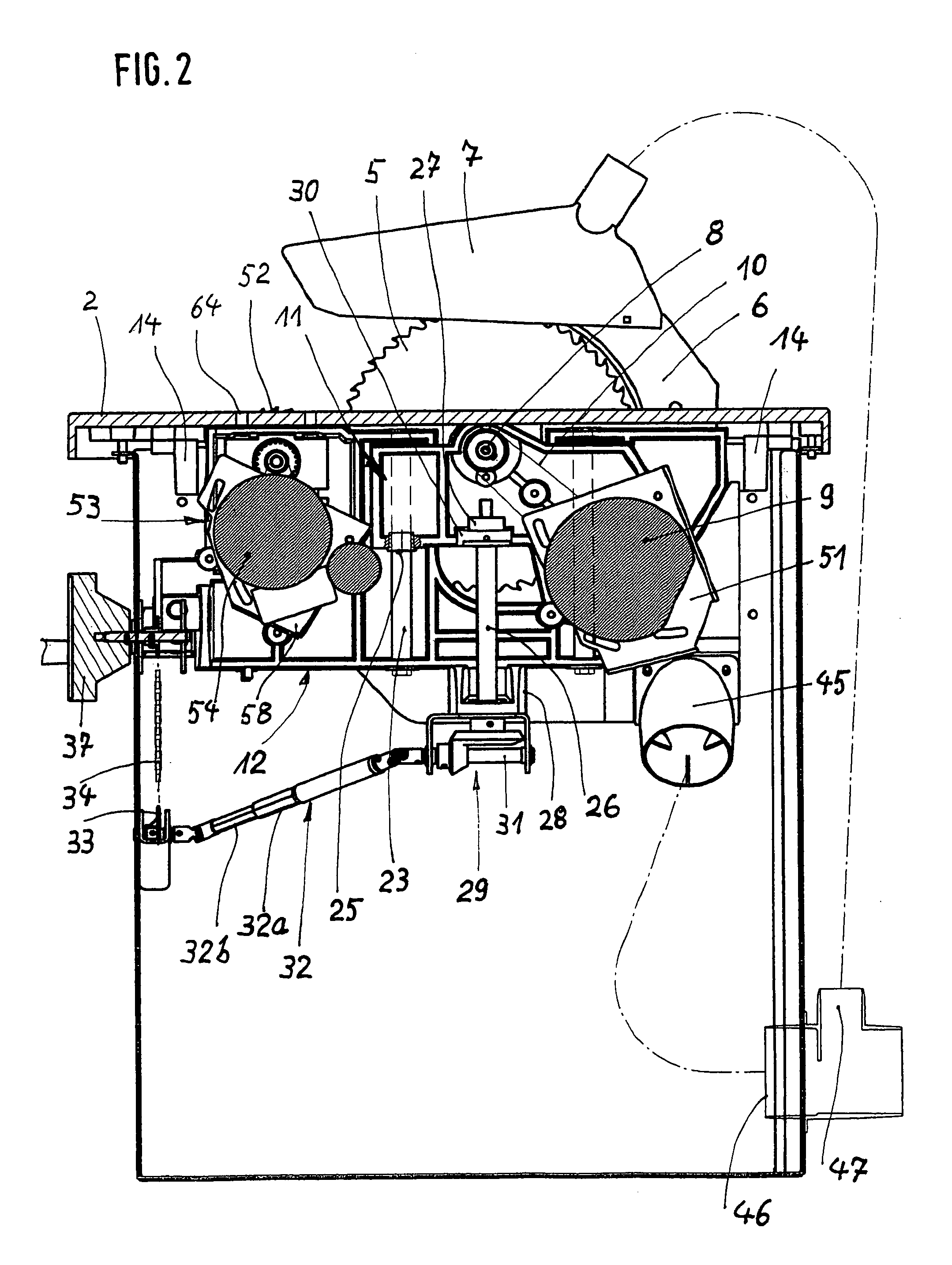
[0016]FIG. 2 shows a longitudinal section of the arrangement according to FIG. 1;

[0017]FIG. 3 shows a schematic top view of the arrangement according to FIG. 1 with the table board removed;

[0018]FIG. 4 shows a perspective view of the swivel frame with integrated tool bracket and the associated bearing brackets;

[0019]FIG. 5 shows a view of a scoring unit which can be attached to the swivel frame; and

[0020]FIG. 6 shows a view of the circular saw according to the invention corresponding to FIG. 1 with fitted inspection cover comprising display units.

DESCRIPTION OF THE PREFERRED EMBODIMENTS

[0021]The present invention is mainly used for circular saws which are provided with a cutting tool having the form of a circular saw blade. The circular saw underlying the drawing possesses a housing-shaped machine frame 1 on which a table board ...


PUM

PropertyMeasurementUnit
degree of freedomaaaaaaaaaa
heightaaaaaaaaaa
edge areasaaaaaaaaaa

Abstract

A circular saw having a machine frame having a table board and a swivel frame arranged underneath the table board, which is swiveled about a swivel axis coplanar with the top side of the table board. The swivel frame accommodates a height adjustable tool bracket carrying at least one cutting tool engaging an associated slot in the table board. The swivel frame in the region of its ends is swivel-suspended on bearing brackets which are mountable on the bottom side of the table board, and are swiveled by an articulated adjusting rod. The tool bracket is height adjusted by an adjusting element which is arranged in driving linkage with an extendable articulated shaft. The adjusting rod and the articulated shaft are operated by cranks mounted on the operating side of the machine frame.

Description

FIELD OF THE INVENTION[0001]The present invention relates to a woodworking machine, in particular a circular saw, provided with a machine frame on which a table board is accommodated, and further provided with a swivel frame arranged underneath the table board, which can be swivelled about a swivel axis coplanar with the top side of the table board, which swivel frame accommodates a height adjustable tool bracket carrying at least one cutting tool engaging an associated slot in the table board, which tool can be clamped onto a shaft drivable by a motor attached to the tool bracket.BACKGROUND OF THE INVENTION[0002]An arrangement of this kind is known, for example, from EP 0 235 683 B1. In this known arrangement, the swivel frame, in the region of its front and rear end, is provided with sliding stones which in pairs engage an associated curved slot of a front and rear stationary end shield which is integrated into the machine frame. Such end shields, at their bottom rim which is conc...

Claims


Application Information

Patent Timeline
Patent Type & Authority Patents(United States)
IPC IPC(8): B26D1/18
CPCB27B5/243B23D45/068Y10T83/857Y10T83/7705Y10T83/773Y10T83/7726
Inventor BAUER, REINHOLD
Owner SCHWEPPACH FAB VON HOLZBEARBEITUNGSMASCHINEN GMBH
Why Eureka
Try Eureka