Broadband antenna

a broadband antenna and antenna technology, applied in the direction of resonant antennas, instruments, burglar alarm mechanical actuation, etc., can solve the problem of too narrow bandwidth on the tag antenna, and achieve the effect of improving read distance and enlarge antenna bandwidth

Active Publication Date: 2009-09-15
IND TECH RES INST
View PDF16 Cites 8 Cited by
  • Summary
  • Abstract
  • Description
  • Claims
  • Application Information

AI Technical Summary

Benefits of technology

[0008]The invention provides a broadband antenna which can perform a multi-coupling feed-in operation by using several radiation bodies to enlarge antenna bandwidth and improve a read distance between the reader and tag.

Problems solved by technology

As a result, an issue of too narrow bandwidth is occurred on the tag antenna.

Method used


Image

  • Broadband antenna
  • Broadband antenna
  • Broadband antenna

Examples


Embodiment Construction

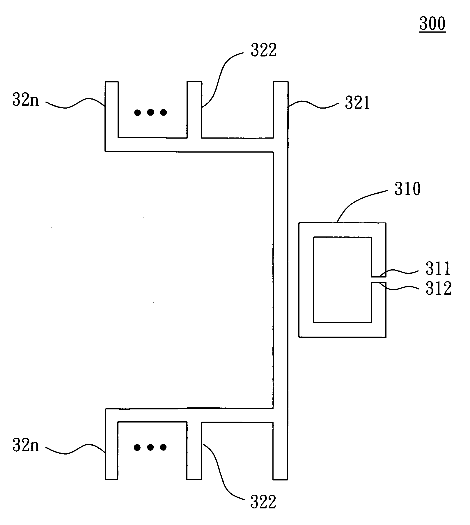
[0019]The invention provides a broadband antenna which can have several resonance frequencies by performing a multi-coupling feed-in operation via a number of radiation bodies. Therefore, the broadband antenna can have larger bandwidth and thus the reader can increase its read distance. Although a broadband tag antenna is taken as an example for the broadband antenna in the following embodiment, the invention is not limited thereto.

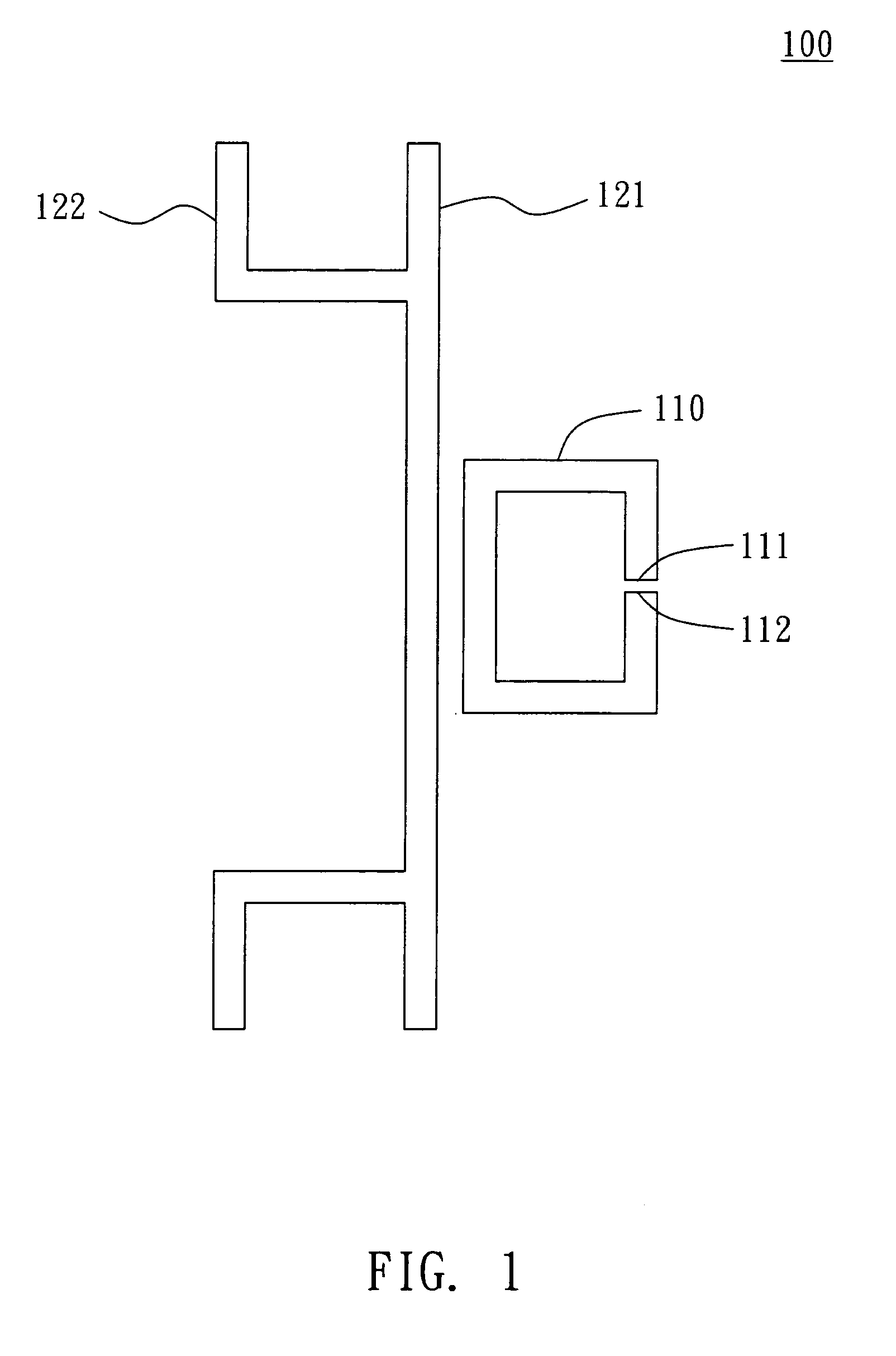
[0020]Referring to FIG. 1, a schematic diagram of a broadband antenna according to a preferred embodiment of the invention is shown. The broadband antenna 100 includes a coupling loop 110 and radiation bodies 121 and 122. The coupling loop 110 has a first feed-in terminal 111 and a second feed-in terminal 112, and a chip (not shown in the figure) is usually electrically coupled between the first feed-in terminal 111 and the second feed-in terminal 112. As shown in FIG. 1, the radiation body 121 is a main body and the radiation body 122 includes two L-shap...


PUM


Abstract

A broadband antenna includes a coupling loop and a number of radiation bodies. The coupling loop is electrically coupled to a chip and the chip records several pieces of data. The radiation bodies respectively form a number of resonance loops with the coupling loop for providing a number of resonance frequencies of the broadband antenna. The coupling loop can feed in signals for reading data in the chip according to the resonance frequencies.

Description

[0001]This application claims the benefit of U.S. provisional application Ser. No. 60 / 801,382, filed May 19, 2006, the subject matter of which is incorporated herein by reference.BACKGROUND OF THE INVENTION[0002]1. Field of the Invention[0003]The invention relates in general to a broadband antenna, and more particularly to a broadband antenna which can enlarge antenna bandwidth by a multi-coupling feed-in mechanism.[0004]2. Description of the Related Art[0005]For example, a radio frequency identification (RFID) system transmits identification information by radio waves such that users can obtain the required information by a wireless way. The RFID system is composed of several RFID tags and a reader. Each RFID tag stores the corresponding identification information, such as product names, sources of goods, or purchase dates for product management.[0006]The RFID tag performs data transmission with the reader by using a tag antenna and a tag chip, and whether the RFID tag can efficien...

Claims


Application Information

Patent Timeline
Patent Type & Authority Patents(United States)
IPC IPC(8): H01Q1/38H01Q5/10H01Q5/371
CPCG06K19/07786H01Q1/2225H01Q5/371H01Q1/38H01Q1/36H01Q1/24H01Q5/00H01Q7/00
Inventor CHANG, CHIH-CHENLO, YUNG-CHIN
Owner IND TECH RES INST
Why Eureka
Try Eureka