Solid-state laser gyro with a mechanically activated gain medium

a laser gyro and gain medium technology, applied in the field of solid-state laser gyro with mechanical activation gain medium, can solve the problems of non-linearity of the frequency response of the laser gyro, the device used to deal with the problem of intermodal competition performs less well at low rotation speed, and the inertial performance degradation, so as to reduce the contrast of the gain grating and therefore the deleterious effect of the gyro measuremen

Inactive Publication Date: 2009-09-15
THALES SA
View PDF18 Cites 13 Cited by
  • Summary
  • Abstract
  • Description
  • Claims
  • Application Information

AI Technical Summary

Benefits of technology

[0010]The principle of the device according to the invention is to modulate the longitudinal position of the active crystal about a mean position, so that the atoms of the crystal are moving relative to the nodes and to the antinodes of the interference pattern formed by the two counterpropagating modes, irrespective of the frequency difference between these two modes. The device according to the invention makes it possible to reduce the contrast of the gain grating, and therefore its deleterious effects on gyro measurements, while not modifying the length of the cavity. The device also makes it possible to attenuate the effects of the backscattering induced by the amplifying medium. Finally, the device according to the invention potentially constitutes a device for dealing with the blind spot, being able, depending on the face, to substitute for or be complementary to the usual mechanical activation device.
[0013]Advantageously, the frequency of the movement is chosen so as to avoid parametric resonant frequencies, which would destabilize the laser. In particular, the said frequency may advantageously be well away from the relaxation frequency or frequencies of the laser.

Problems solved by technology

It has been shown that this population inversion grating has deleterious effects for gyro measurements, for two main reasons:it exacerbates the competition between the counterpropagating modes, preventing in most cases the beat regime, which is the operating regime to be established in a gyrometer; andit induces a non-linearity in the frequency response when the laser is rotating, thereby degrading the inertial performance.
However, the devices used to deal with the problem of intermodal competition perform less well at low rotation speeds and do not in general get round the problem of non-linearity of the frequency response of the laser gyro.
It is then necessary to control the stability of the bias used, otherwise the inertial performance is limited.
The latter technique requires the birefringence in the cavity to be controlled, which means it is difficult to use when high inertial performance is required.

Method used


Image

  • Solid-state laser gyro with a mechanically activated gain medium
  • Solid-state laser gyro with a mechanically activated gain medium
  • Solid-state laser gyro with a mechanically activated gain medium

Examples


Embodiment Construction

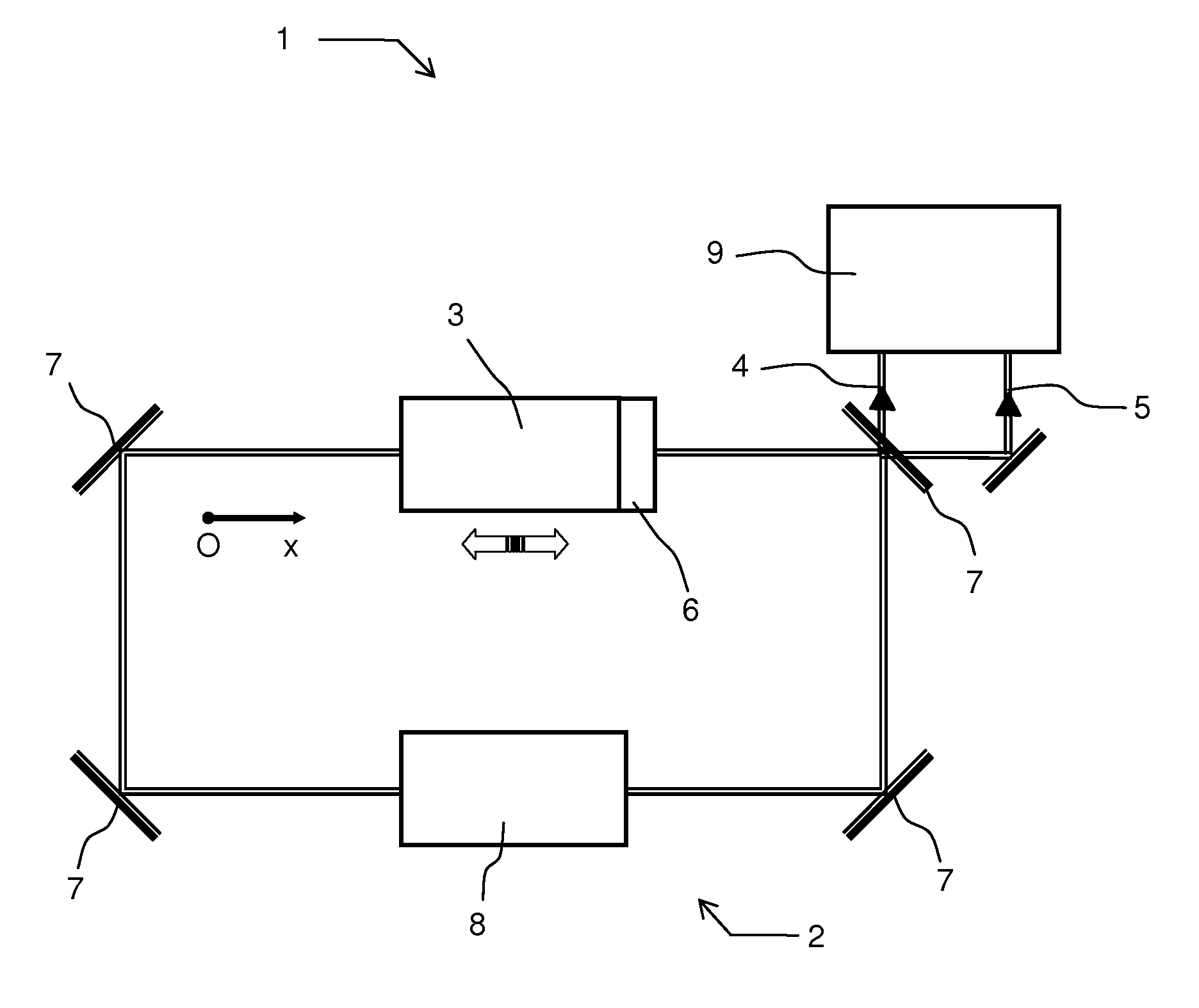
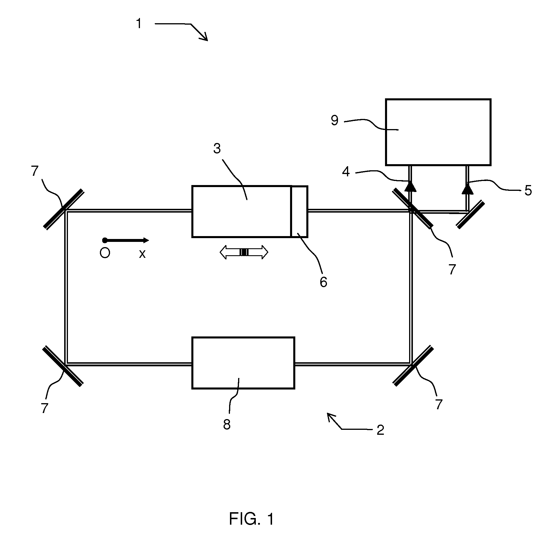
[0021]FIG. 1 shows a general view of a laser gyro 1 according to the invention. It comprises, conventionally:[0022]a ring cavity 2 composed of mirrors 7, in which two optical modes 4 and 5, called counterpropagating modes, circulate in opposite directions one with respect to the other;[0023]a solid-state amplifying medium 3 through which said modes pass;[0024]measurement means 9 comprising at least optical means for making the two optical modes interfere and calculation means for determining the angular displacement or the angular velocity of the cavity on the basis of the measurement of the interference patterns obtained; and[0025]optionally, other optical systems such as, for example, devices 8 for stabilizing the intensity of the counterpropagating modes.

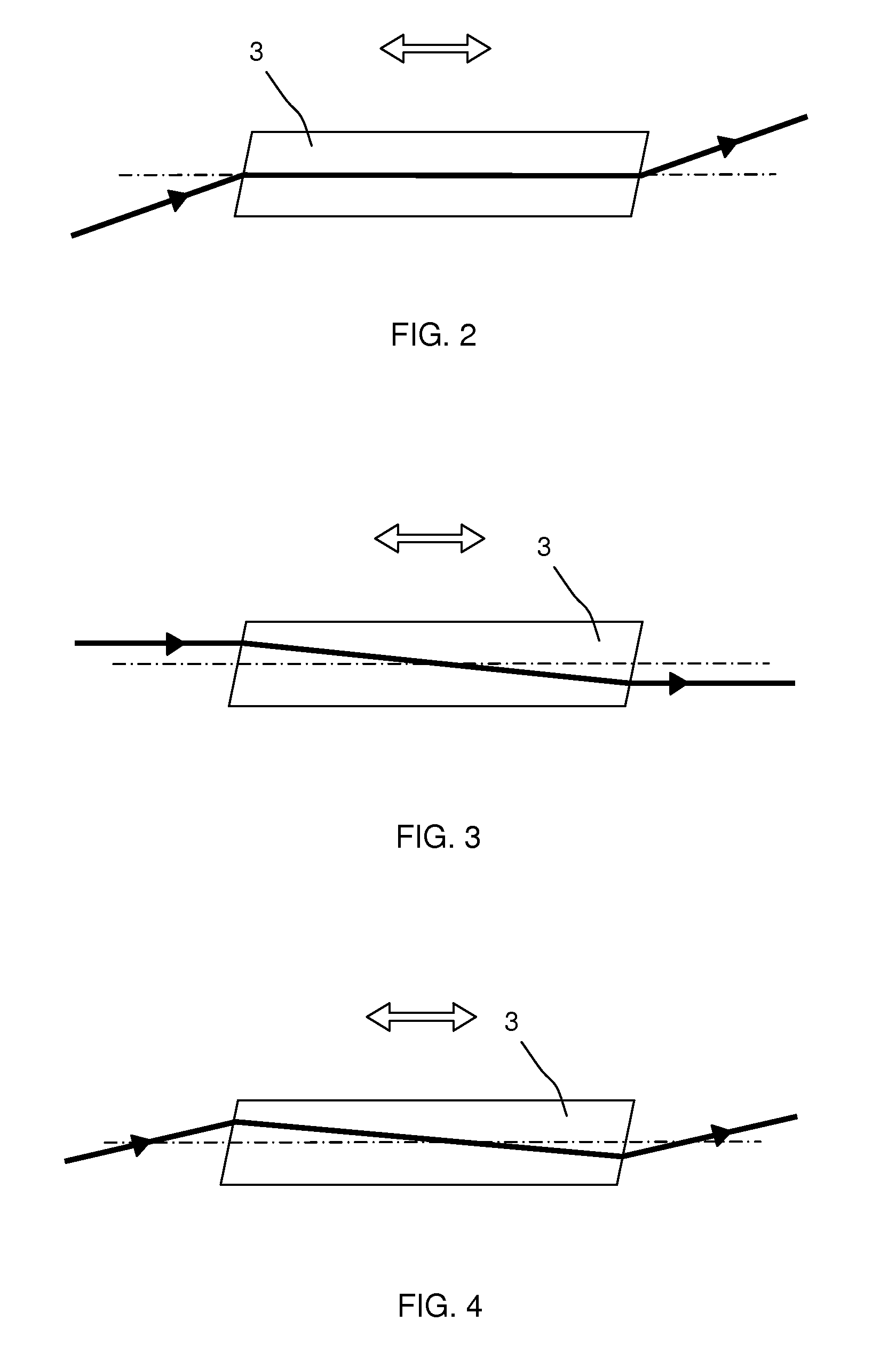
[0026]In addition, the amplifying medium is coupled to an electromechanical device 6 imparting on said amplifying medium a time-dependent periodic translational movement denoted by xc(t) along an axis Ox substantially parallel to...


PUM


Abstract

The field of the invention is that of solid-state ring lasers or laser gyros. The laser gyro according to the invention comprises at least one optical cavity in the form of a ring and a solid-state amplifying medium which are designed so that two counterpropagating optical modes can propagate in opposite directions one with respect to the other inside said optical cavity and pass through the amplifying medium, said amplifying medium being coupled to an electromechanical device imparting on said amplifying medium a periodic translational movement along an axis substantially parallel to the direction of propagation of said optical modes. Thus, the population inversion grating, written by the standing wave into the amplifying medium, which disturbs the nominal operation of the laser gyro, is greatly attenuated.

Description

RELATED APPLICATIONS[0001]The present application is based on, and claims priority from, France Application Number 06 07394, filed Aug. 18, 2006, the disclosure of which is hereby incorporated by reference herein in its entirety.BACKGROUND OF THE INVENTION[0002]1. Field of the Invention[0003]The field of the invention is that of solid-state ring lasers, also called laser gyros. Almost all laser gyros use a gaseous amplifying medium, which is usually a mixture of helium and neon. However, it is possible to use a laser gyro having a solid-state amplifying medium in which the gaseous amplifying medium is replaced with a solid-state element, for example a neodymium-doped YAG (yttrium aluminium garnet) matrix.[0004]2. Description of the Prior Art[0005]The operating principle of a laser gyro is based on the Sagnac effect of a bidirectional ring laser cavity undergoing a rotational movement. The Sagnac effect induces a frequency difference Q between two counterpropagating optical emission ...

Claims


Application Information

Patent Timeline
Patent Type & Authority Patents(United States)
IPC IPC(8): G01C19/64
CPCG01C19/66
Inventor SCHWARTZ, SYLVAINGUTTY, FRANCOISPOCHOLLE, JEAN-PAULFEUGNET, GILLES
Owner THALES SA
Why Eureka
Try Eureka