Automated quoting of molds and molded parts

a technology of automatic quoting and molds, applied in the field of mold manufacturing, can solve the problems of significant time delay, inability to manually control machining operations, and high cost of obtaining the desired injection mold

Inactive Publication Date: 2009-09-15
PROTOLABS INC
View PDF20 Cites 55 Cited by
  • Summary
  • Abstract
  • Description
  • Claims
  • Application Information

AI Technical Summary

Problems solved by technology

Because of the large number of technical decisions involved and considerable time spent by highly skilled moldmakers in analyzing in detail the part geometry by visual inspection, obtaining a desired injection mold has generally been quite expensive and involved a significant time delay.
Also, in most moldmaking companies machining operations are not manually controlled.
While existing CAD / CAM software packages allow designers and CNC machinists to work with geometrically complex parts, they are still far from completely automating the designer's work.
The downside of such versatility, when applied to moldmaking, is that it results in long and labor intensive working sessions to produce mold designs and CNC machining instructions for many custom parts, including parts lending themselves to straight pull molding.
The fidelity with which plastic parts can be manufactured is limited by the finite precision of mills and cutting tools used to machine the mold, and by shrinkage of plastic materials (slightly changing the shape and dimensions of the injection molded parts as they cool down and undergo stress relaxation in a way that is largely but not entirely predictable).
Oftentimes, however, additional factors come into play that can result in more significant deviations of injection molded plastic parts from the submitted design geometry.
For example, very thin ribs in the part can be made by cutting deep and narrow grooves in the mold, but may require an endmill with an impractically large length to diameter ratio.
Machining of angles between adjacent faces joined by small radius fillets (and, especially, of angles left without a fillet) may result in similar difficulties.
Exact rendering of such features may substantially increase the cost of the mold, and even make its fabrication impractical with the technology available to the moldmaker.
As plastic parts often have many unnamed (and hard to name) features, pure verbal communication not supported by visualization of the part can be awkward and misleading.
Such meetings take a considerable amount of time, both from moldmakers and their customers, and increase business costs.
For obvious reasons the informal quoting method is prone to human errors.
If the request for quotation results in the job order, such errors will most likely become apparent during mold design and machining, or even after the mold is finished and used for manufacturing the first plastic parts.
The price of such mistakes in terms of the lost time and effort, as well as in terms of strained customer relations, may be rather high.

Method used


Image

  • Automated quoting of molds and molded parts
  • Automated quoting of molds and molded parts
  • Automated quoting of molds and molded parts

Examples


Embodiment Construction

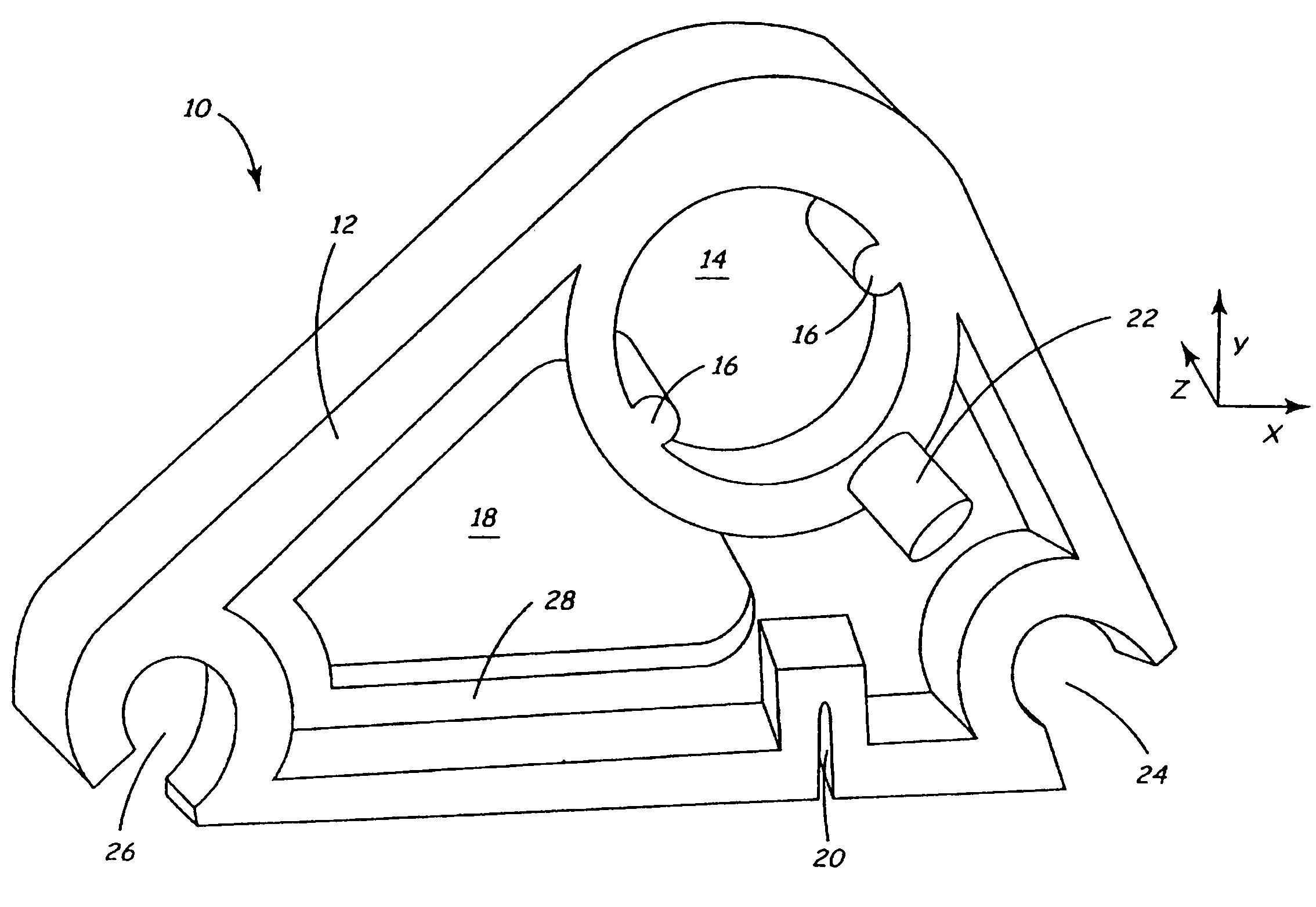
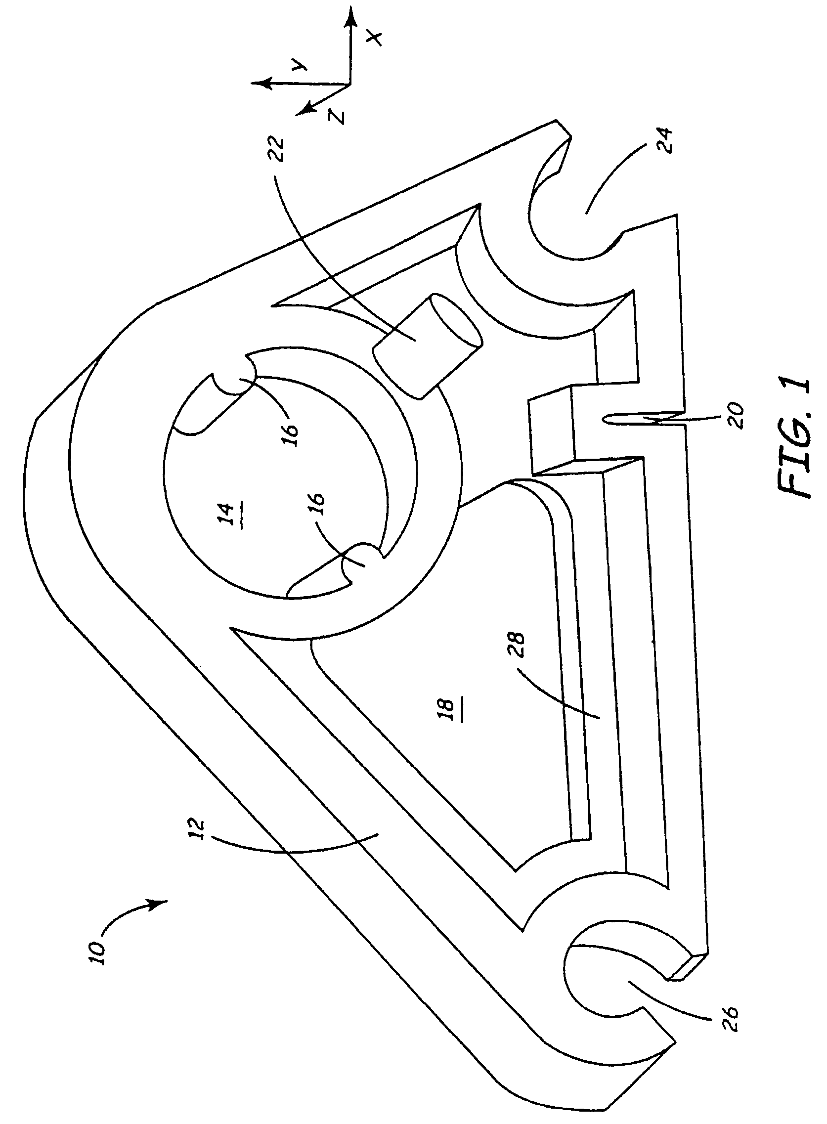
[0027]The present invention will be described with reference to an exemplary part 10 shown in FIG. 1. FIG. 1 represents a “cam” part 10 designed by the customer. In part because the cam 10 is custom-designed (i.e., not a staple article of commerce) by or for this particular customer, the cam 10 includes numerous features, none of which have commonly accepted names. For purposes of discussion, we will give names to several of these features, including a part outline flange 12, a circular opening 14 with two rotation pins 16, a non-circular opening 18, a notch 20, a rib 22, a 60° corner hole 24, a 30° corner hole 26, and a partial web 28. However, workers skilled in the art will appreciate that the customer may in fact have no name or may have a very different name for any of these features.

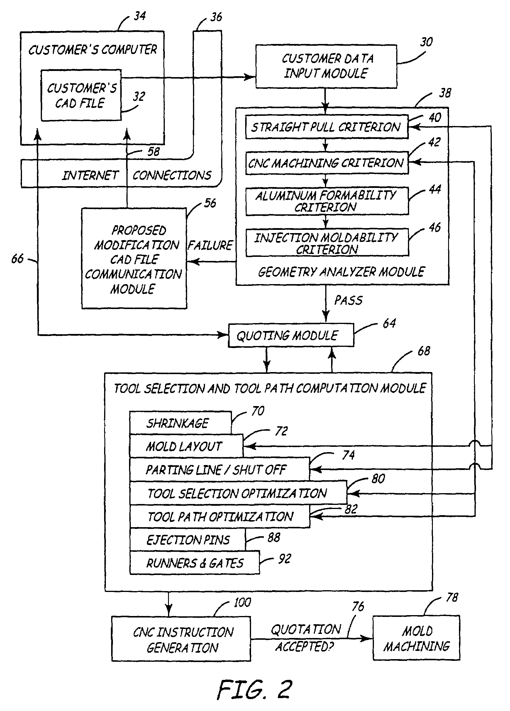
[0028]FIG. 2 is a flow chart showing how the present invention is used to manufacture the customer's part. The first step involves a Customer Data Input module 30. Thus, the starting input for the ...


PUM

PropertyMeasurementUnit
draft anglesaaaaaaaaaa
cutting depthaaaaaaaaaa
heightaaaaaaaaaa

Abstract

Automated, custom mold manufacture for a part begins by creating and storing a collection of information of standard tool geometries and surface profiles machinable by each of the standard tool geometries. A customer sends a CAD file for the part to be molded to the system. The system assesses the CAD file to determine various pieces of mold manufacturing information. One or more acceptability criteria are applied to the part, such as whether the part can be manufactured in a two-piece, straight-pull mold, and whether the mold can by CNC machined out of aluminum. If not, the system sends a file to the customer graphically indicating which portions of the part need modification to be manufacturability. The system provides the customer with a quotation form, that allows the customer to select several parameters, such as number of cavities, surface finish and material, which an independent of the shape of the part.

Description

CROSS-REFERENCE TO RELATED APPLICATION(S)[0001]The present application is a continuation of U.S. patent application Ser. No. 10 / 325,286, filed Dec. 19, 2002 and entitled AUTOMATED QUOTING OF MOLDS AND MOLDED PARTS, now issued as U.S. Pat. No. 6,836,699, incorporated by reference herein, which is a continuation-in-part of U.S. patent application No. 10 / 056,755 of Lawrence J. Lukis et al., filed Jan. 24, 2002, entitled AUTOMATED CUSTOM MOLD MANUFACTURE, now issued as U.S. Pat. No. 6,701,200, incorporated by reference herein, which claims priority from provisional U.S. patent application Ser. No. 60 / 344,187, filed Dec. 27, 2001, entitled AUTOMATED MANUFACTURE OF STRAIGHT PULL MOLDS FOR CUSTOM PLASTIC PARTS. This application also claims priority (through application No. 10 / 325,286) from provisional patent application Ser. No. 60 / 386,658 of Lawrence J. Lukis et al., filed Jun. 5, 2002, entitled IMPROVED PROTOTYPE QUOTING.BACKGROUND OF THE INVENTION[0002]The present invention relates to t...

Claims


Application Information

Patent Timeline
Patent Type & Authority Patents(United States)
IPC IPC(8): G06F19/00B22C19/04B29C33/38G06Q30/00
CPCB22C19/04G06Q30/06B29C33/3835
Inventor LUKIS, LAWRENCE J.DREIZIN, YURI A.GILBERT, JOHN M.
Owner PROTOLABS INC
Why Eureka
Try Eureka