
Suspension structure for small vehicle

a suspension structure and small vehicle technology, applied in the direction of resilient suspensions, interconnection systems, vehicle components, etc., can solve the problems of increasing the weight of the vehicle body, the structure of the vehicle body becomes complicated, and the stabilizer may come into contact with obstacles, so as to reduce the weight, the stabilizer can be downsized, and the configuration is simple.

Inactive Publication Date: 2009-09-22
HONDA MOTOR CO LTD
View PDF3 Cites 30 Cited by
  • Summary
  • Abstract
  • Description
  • Claims
  • Application Information

AI Technical Summary

Benefits of technology

The present invention provides a suspension structure for small vehicles that includes a stabilizer for connecting the suspension arms, cushions for supporting the suspension arms, and an arm supporting frame for swingably supporting the suspension arms. The stabilizer can be arranged inside the suspension arms or the upper arms and can be protected by the vehicle body frame. The stabilizer can be downsized and a compact, light weight, and simple configuration can be achieved. The suspension structure can be formed into an independent suspension type with a double wishbone structure or a structure in which the stabilizer is arranged inside the upper arms or lower arms. The stabilizer can be easily arranged without interference with the arms. The technical effects of the invention include improved stability, reduced weight, and a simplified structure.

Problems solved by technology

Therefore, the stabilizer may come into contact with obstacles such as rocks.
However, when strengthening the stabilizer by itself or providing another member for protecting the stabilizer, there are cases such that the weight of the vehicle body is increased or the number of components is increased, so that the structure of the vehicle body becomes complicated.

Method used


Image

  • Suspension structure for small vehicle
  • Suspension structure for small vehicle
  • Suspension structure for small vehicle

Examples


Embodiment Construction

[0027]An embodiment of the present invention will now be described with reference to the accompanying drawings. The same reference numerals will be used to identify the same or similar elements throughout the several views. It should be noted that each of the drawings should be viewed in the direction of orientation of the reference numerals.

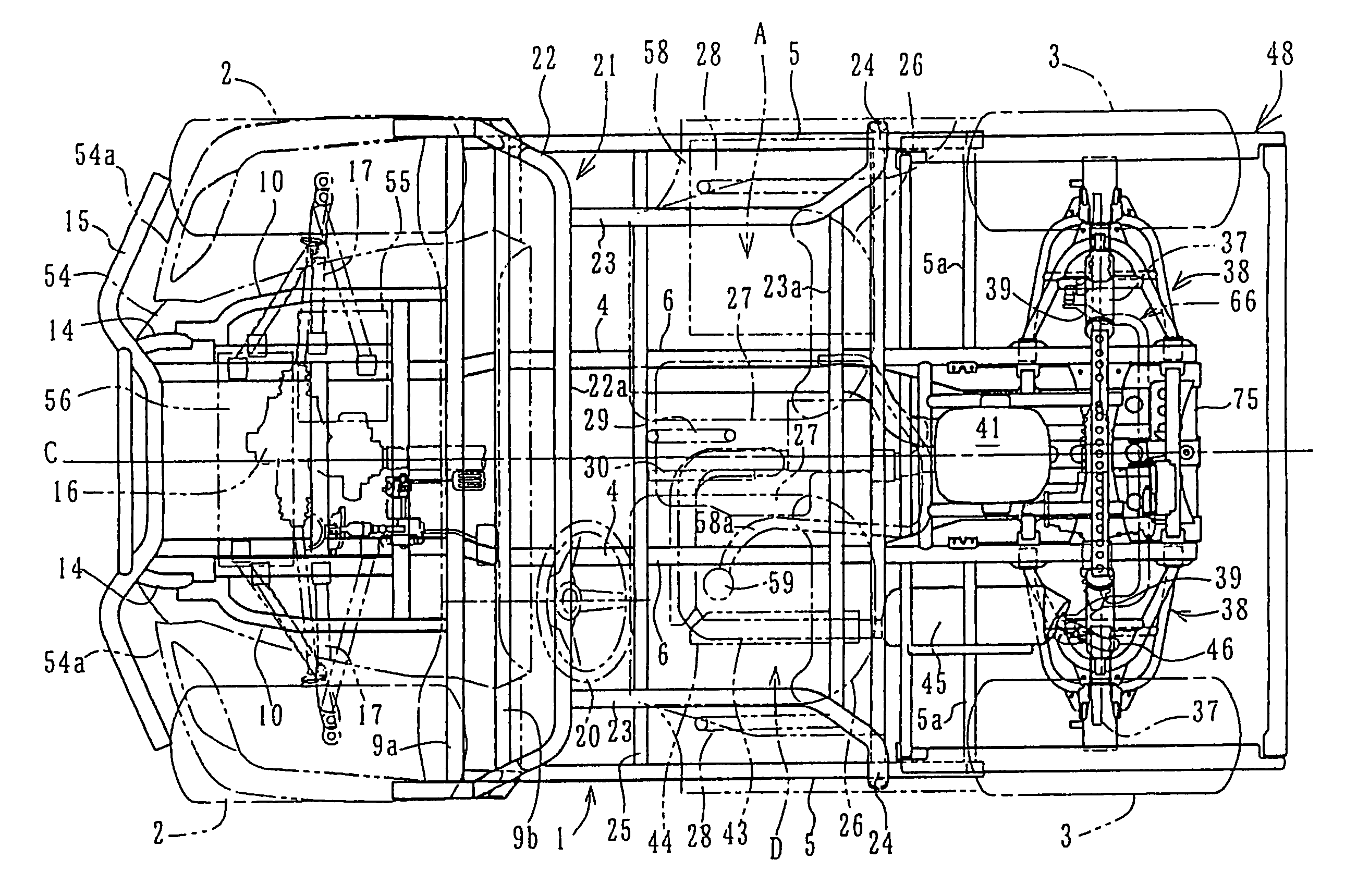
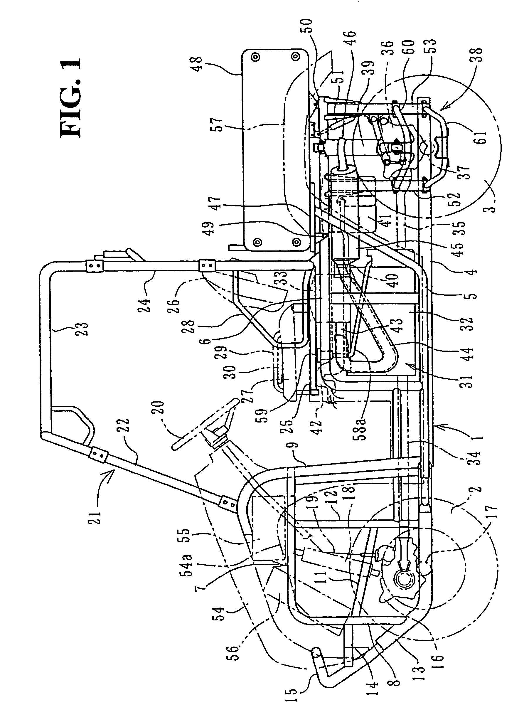
[0028]FIG. 1 is a side view of a small vehicle or the like according to an embodiment of the present invention. This small vehicle is configured for rough-terrain traveling and includes four independently suspended front and rear wheels and two left and right seats. Specifically, a pair of front wheels 2 and a pair of rear wheels 3 are suspended independently in the front and rear of a vehicle body frame 1 so that it can be used as a golf cart or the like.

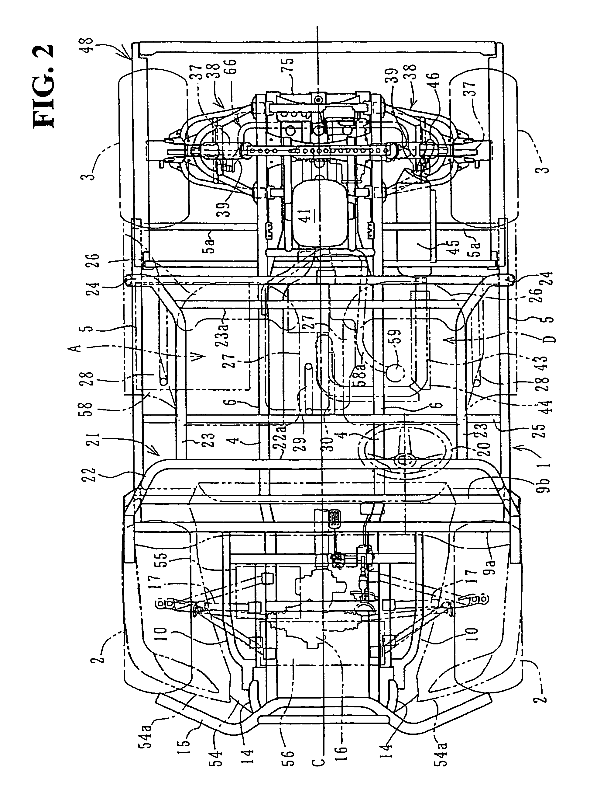
[0029]The vehicle body frame 1 includes center frames 4 extending in a fore-and-aft direction over substantially an entire length of the vehicle body along a center portion of vehicle width. Si...


PUM


Abstract

In rear wheel suspensions, which suspend left and right rear wheels independently, to downsize, reduce in weight and simplify a stabilizer without specifically strengthening the same. Upper and lower arms which form suspension arms in a double wishbone structure are swingably supported by a front arm supporting frame and a rear arm supporting frame provided on front and rear sides of a rear cushion. A cross portion of a stabilizer is swingably supported by the stabilizer brackets provided on a front surface of the rear arm supporting frame, and left and right arm portions extending toward the front are arranged upwardly of the left and right upper arms so as to be placed inside thereof in plan view respectively, and distal ends thereof are connected to the left and right upper arms respectively.

Description

CROSS-REFERENCE TO RELATED APPLICATIONS[0001]This nonprovisional application claims priority under 35 U.S.C. § 119(a) on Patent Application No. 2005-278223, filed in Japan on Sep. 26, 2005, the entirety of which is incorporated herein by reference.BACKGROUND OF THE INVENTION[0002]1. Field of the Invention[0003]The present invention relates to a suspension structure for a small vehicle that is suitable for rough-terrain traveling, such as a golf cart or a buggy vehicle.[0004]2. Description of Background Art[0005]In a rear wheel suspension for a small vehicle used for rough-terrain traveling or the like, there is known a structure in which a stabilizer for connecting left and right suspension arms is composed of a twisted portion extending widthwise of the vehicle and arm portions bent at left and right portions thereof toward the rear. The left and right arm portions are arranged so as to protrude outward toward left and right sides of a vehicle body frame (see JP-A-63-134390).[0006]...

Claims


Application Information

Patent Timeline
Patent Type & Authority Patents(United States)
IPC IPC(8): B60G21/055B60G3/18B60G7/00
CPCB60G21/055B60G21/0551B60G2204/1224B60G2204/1222
Inventor KINJYO, TOSHIKIOKANIWA, TAKESHITAGAMI, TAKUYA
Owner HONDA MOTOR CO LTD
Learn More