Low voltage logic operation using higher voltage supply levels

a logic operation and high voltage technology, applied in the direction of power consumption reduction, pulse technique, instruments, etc., can solve the problems of increasing the power dissipation of microprocessors, limiting the amount of current flowing through these devices, and it is extremely difficult to reduce the parasitic resistance to less than 1 m megaohm without significantly increasing material and associated processing costs. , to achieve the effect of reducing the difference in current consumption

Active Publication Date: 2009-09-22
MARVELL ASIA PTE LTD
View PDF8 Cites 18 Cited by
  • Summary
  • Abstract
  • Description
  • Claims
  • Application Information

AI Technical Summary

Benefits of technology

[0008]A circuit comprises a first module and a second module that communicates with the first module. The first and second modules are connected in series between first and second reference potentials. A current balancing module communicates with a node between the first and second modules and reduces a difference in current consumption between the first and second modules.

Problems solved by technology

Power dissipation of microprocessors has also increased.
Physical barriers are beginning to limit the amount of current flowing through these devices.
One barrier relates to the voltage drop associated with the distribution of power to these microprocessors.
In reality, it is extremely difficult to lower the parasitic resistance to less than 1 MΩ megaohm without significantly increasing material and associated processing costs.

Method used


Image

  • Low voltage logic operation using higher voltage supply levels
  • Low voltage logic operation using higher voltage supply levels
  • Low voltage logic operation using higher voltage supply levels

Examples


Embodiment Construction

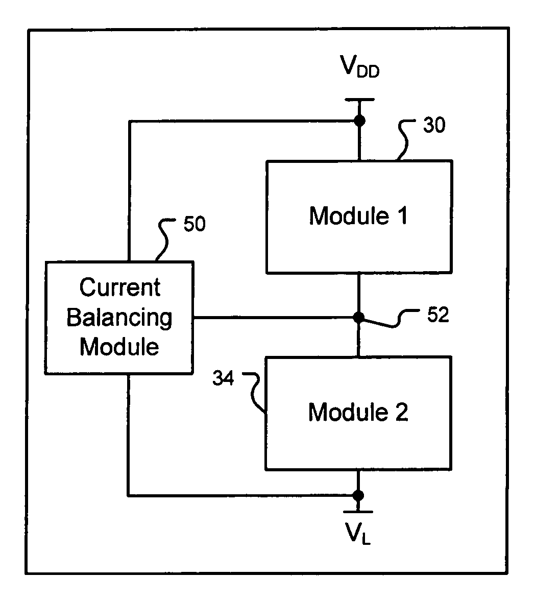
[0086]The following description of the preferred embodiment(s) is merely exemplary in nature and is in no way intended to limit the invention, its application, or uses. For purposes of clarity, the same reference numbers will be used in the drawings to identify similar elements. As used herein, the term module or modules refers to an application specific integrated circuit (ASIC), an electronic circuit, a processor (shared, dedicated, or group) and memory that execute one or more software or firmware programs, a microprocessor subsystem, a combinatorial logic circuit, complex logic macros and / or other suitable components that provide the described functionality.

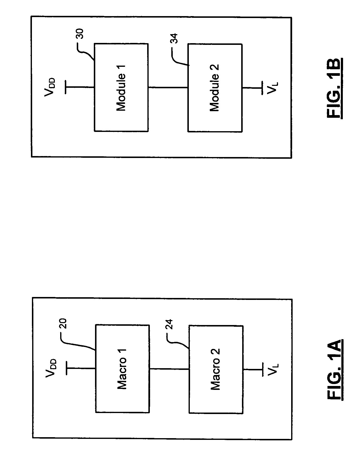
[0087]Referring now to FIGS. 1A and 1B, the present invention stacks groups of devices (such as complex logic macros and / or modules) on top of each other to overcome practical parasitic resistance barriers. In FIG. 1A, complex logic macros 20 and 24 are stacked on top of another and connected between VDD and VL. In some imple...


PUM


Abstract

A circuit comprises a first module and a second module that communicates with the first module. The first and second modules are connected in series between first and second reference potentials. A current balancing module communicates with a node between the first and second modules and reduces a difference in current consumption between the first and second modules.

Description

CROSS-REFERENCE TO RELATED APPLICATIONS[0001]This application claims the benefit of U.S. Provisional Application No. 60 / 631,552, filed on Nov. 29, 2004, and U.S. Provisional Application No. 60 / 663,933, filed on Mar. 21, 2005, which are hereby incorporated herein by reference in their entirety.FIELD OF THE INVENTION[0002]The present invention relates to the operation of low voltage complex logic macros and / or modules using higher voltage supply levels and lower current levels.BACKGROUND OF THE INVENTION[0003]Complementary metal oxide semiconductor (CMOS) process scaling over the past decade has produced smaller devices through the integration of increasing numbers of transistors. For example, current microprocessors are more than a thousand times more powerful than microprocessors made a decade ago.[0004]Power dissipation of microprocessors has also increased. Some microprocessors now dissipate more than 100 W. Modem processors built using low voltage CMOS processes employ a supply v...

Claims


Application Information

Patent Timeline
Patent Type & Authority Patents(United States)
IPC IPC(8): G06F1/26
CPCG06F1/26H02J1/08H03K19/1731H03K19/0008H02J7/0016
Inventor SUTARDJA, SEHAT
Owner MARVELL ASIA PTE LTD
Why Eureka
Try Eureka