Connector structure with a u-shaped cross section having a male terminal and a female terminal

a technology of connecting structure and cross section, which is applied in the direction of coupling contact member, coupling device connection, securing/insulating coupling contact member, etc., can solve the problems of reducing the unable to obtain the desired strength of the terminal, and few types of connectors that are suitable, etc., to achieve excellent heat dissipation and good connection

Inactive Publication Date: 2009-09-29
HITACHI METALS LTD
View PDF40 Cites 17 Cited by
  • Summary
  • Abstract
  • Description
  • Claims
  • Application Information

AI Technical Summary

Benefits of technology

[0020]Accordingly, an object of the invention is to provide a connector structure having a male terminal and a female terminal in which the male terminal has an excellent heat dissipation property during the large current flow and a good connection with an external device.
[0021]Another object of the invention is to provide a connector structure having a male terminal and a female terminal in which the female terminal is provided with a spring which keeps a good contacting force for fixing the male terminal at a high temperature, without increasing a terminal inserting force of the male terminal.
[0046]According to the present invention, the male terminal can be provided with an excellent heat dissipation property during the large current flow and a good connection with an external device can be realized.
[0047]Further, according to the present invention, the female terminal can be provided with a spring which keeps a good contacting force for fixing the male terminal even at a high temperature, without increasing a terminal inserting force of the male terminal.

Problems solved by technology

However, there are few kinds of connectors that are suitable for the large current flow.
However, since a relationship between an electrical conductivity and strength of the terminal material is a trade-off, there is a tendency that the strength of the terminal is reduced when the high conductivity material is used for forming the terminal.
For example, if the terminal is formed by using a copper with a conductivity of 90% or more, a desired strength of the terminal cannot be obtained.
However, since the conventional male terminal 50 shown in FIG. 11 is composed of a single plate, a surface area there of is small, so that the heat dissipation property is not excellent.
Accordingly, there is a disadvantage in that a temperature of the terminal is elevated during the large current flow, thereby influencing on a housing resin or peripheral devices of the connector.
However, in the case where the male terminal having the hollow and rectangular shape is used, while the heat dissipation during the current flow can be improved, it is difficult to conduct a bus connection which is typically used in the connection with a component at the device side such as an inverter.
In such a case, it is significantly difficult to bend the terminal with the rectangular structure for the bus connection, since cracks may be generated.
Therefore, the problems in the conventional male terminal cannot be solved by the hollow and rectangular structure male terminal.
However, when the conventional female terminal is used as a connector terminal for a vehicle, there is a following disadvantage.
However, when the spring with high contacting force is provided, there is a disadvantage in that a force required for inserting the male terminal into the female terminal (terminal inserting force) is increased, so that the insertion of the male terminal into the female terminal will be difficult.

Method used


Image

  • Connector structure with a u-shaped cross section having a male terminal and a female terminal
  • Connector structure with a u-shaped cross section having a male terminal and a female terminal
  • Connector structure with a u-shaped cross section having a male terminal and a female terminal

Examples


Embodiment Construction

[0062]Next, a connector structure having a male terminal and a female terminal in the preferred embodiment according to the invention will be explained in more detailed in conjunction with the appended drawings.

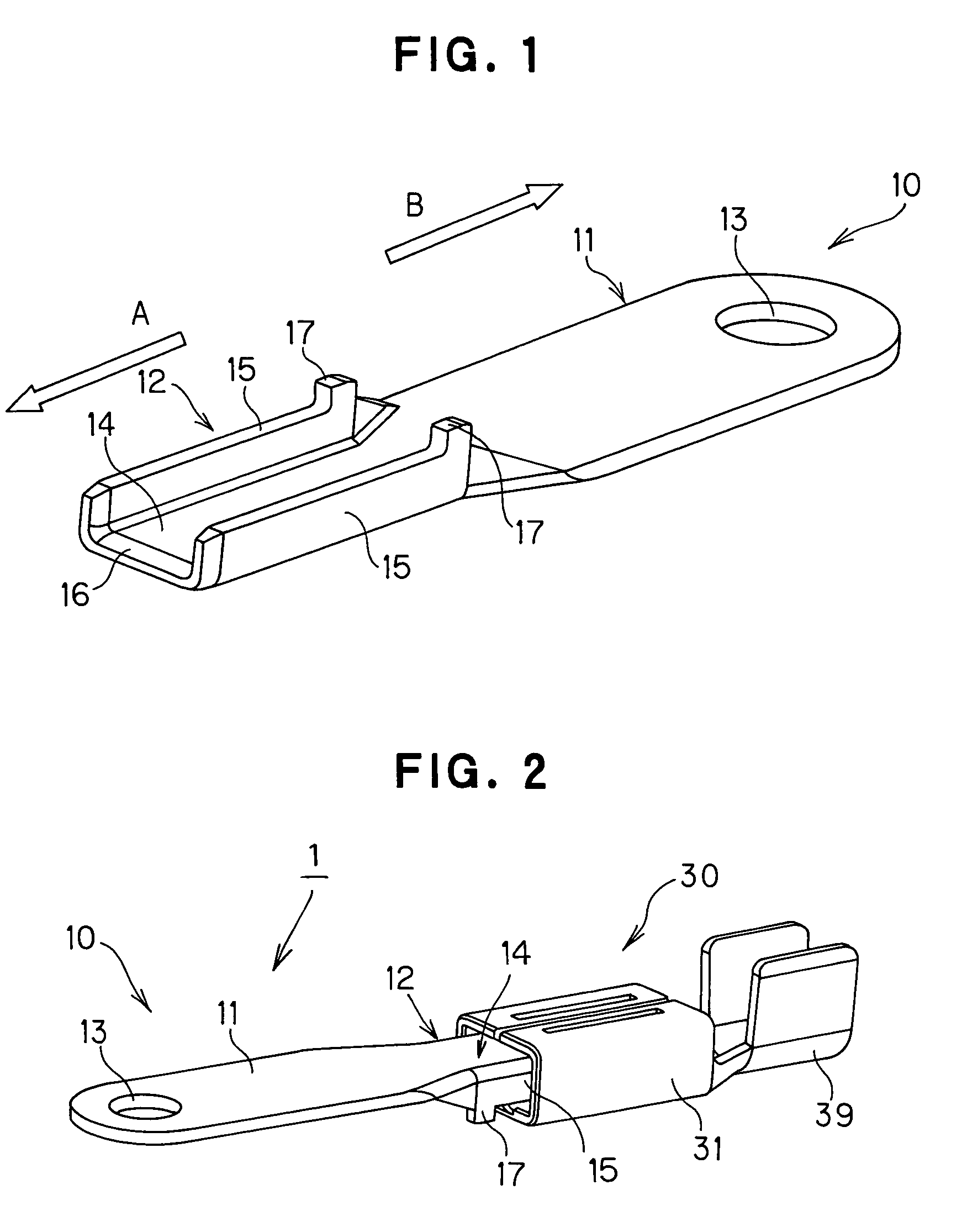
[0063]FIG. 1 is a perspective view showing a male terminal of a connector in the preferred embodiment according to the invention.

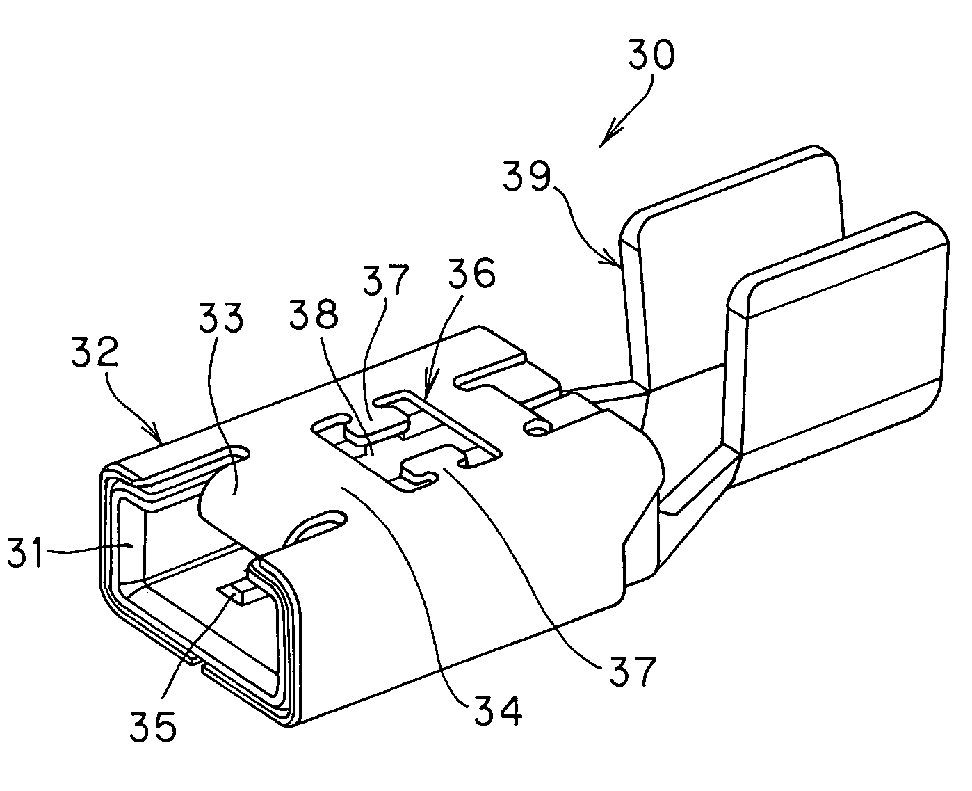
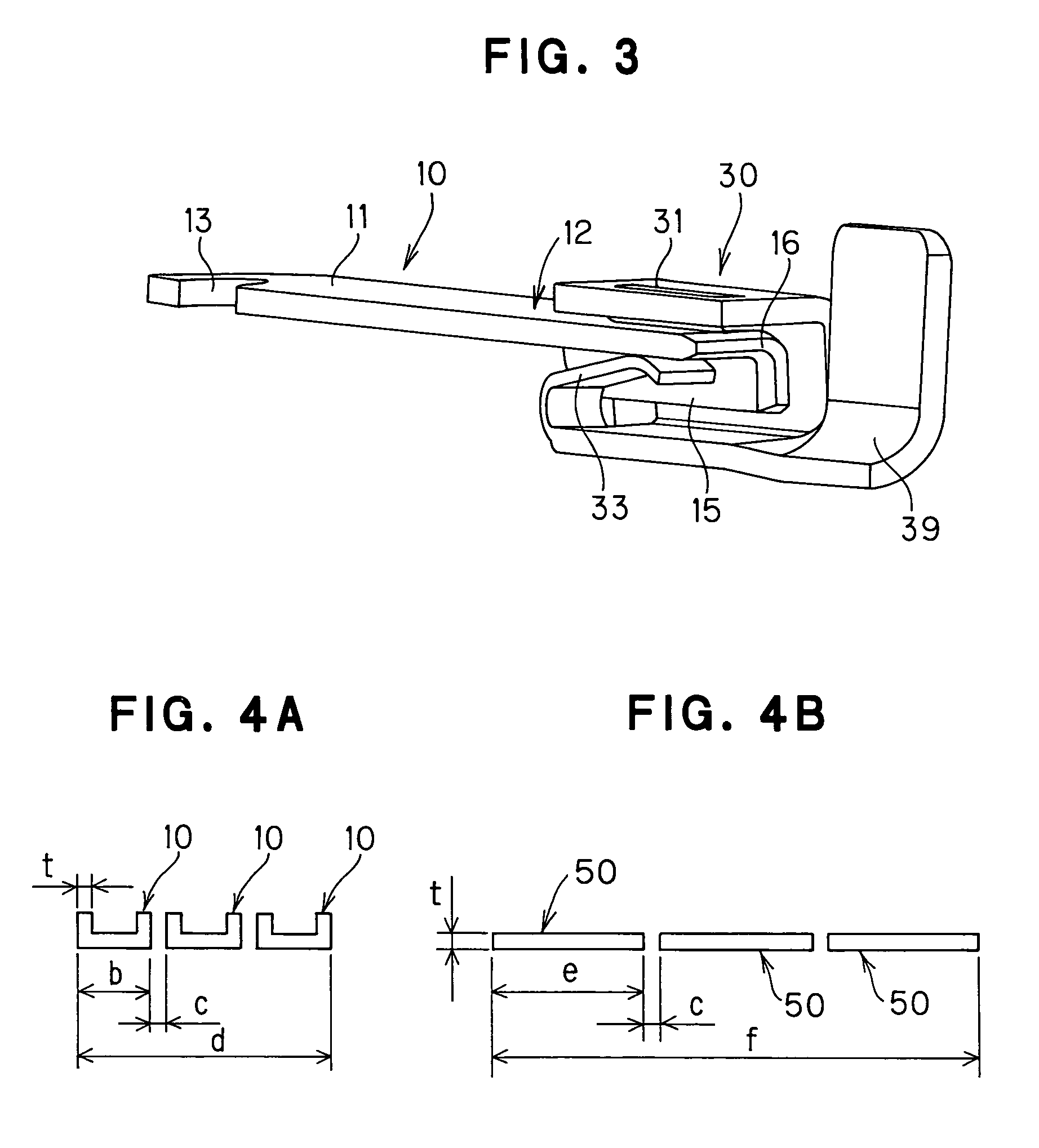
[0064]FIG. 2 is a perspective view showing a connector 1 in which the male terminal 10 in the preferred embodiment is inserted into a female terminal 30.

[0065]In the preferred embodiment of the present invention, as shown in FIG. 1, a male terminal 10 composed of a narrow plate member comprises a wire connecting portion 11 at one end thereof (indicated by an arrow B), to be connected to an electric wire (of the other electrical apparatus), and an inserting contact portion 12 at another end thereof (indicated by an arrow A), to be inserted into the female terminal 30 shown in FIG. 2. In the preferred embodiment of the present invention, the inserting...


PUM


Abstract

A male terminal 10 has a wire connecting portion 13 at one end to be connected to an electric wire, and an inserting contact portion 12 at another end to be inserted into a female terminal 30. A plate member of the inserting contact portion 12 is bent to have a U-shape cross section. The female terminal 30 has a terminal energizing portion 31 composed of a high conductivity material having a frame structure for accommodating the male terminal 10, a terminal box 32 composed of a material having a strength higher than that of the high conductivity material of the terminal energizing portion 31 for covering the terminal energizing portion 31, and a spring 33 located within the terminal energizing portion 31 for fixing the male terminal 10. The spring 33 is formed integrally with the terminal box 32.

Description

[0001]The present application is based on Japanese patent application Nos. 2005-380303 and 2005-380304, the entire contents of which are incorporated herein by reference.BACKGROUND OF THE INVENTION[0002]1. Field of the Invention[0003]The present invention relates to a connector structure having an electric terminal for flowing a large current, in more particularly, to a connector structure having a male terminal and a female terminal in that the male terminal is connected to the female terminal by inserting the male terminal into the female terminal.[0004]2. Description of the Related Art[0005]Nowadays, HEV (Hybrid Electric Vehicle) attracts a great deal of interest, since the HEV can provide an effect of reducing exhaust of harmful gas and a large fuel saving benefit. A connection between an inverter and a motor for driving the HEV is conducted by a connector, and a large current greater than 100 A may be flown in accordance with the system of the HEV. In accordance with developmen...

Claims


Application Information

Patent Timeline
Patent Type & Authority Patents(United States)
IPC IPC(8): H01R13/02H01R9/24
CPCH01R13/03H01R13/20H01R13/15H01R11/12H01R13/18H01R13/187
Inventor OKA, TAICHINAKAJIMA, KENJITAKEHARA, HIDEAKISHIMIZU, MICHIAKIITO, SHINJISUMI, TORU
Owner HITACHI METALS LTD
Why Eureka
Try Eureka