Device, network, and system for forwarding frames between geographically dispersed user networks

a user network and frame forwarding technology, applied in the field of device, network and system for forwarding frames between geographically dispersed user networks, can solve the problems of unsatisfactory needs, inability to meet them, and inability to efficiently manage the resources of the carrier network, so as to achieve efficient operation of the carrier network

Inactive Publication Date: 2009-09-29
FUJITSU LTD
View PDF16 Cites 38 Cited by
  • Summary
  • Abstract
  • Description
  • Claims
  • Application Information

AI Technical Summary

Benefits of technology

[0018]In view of the foregoing, it is an object of the present invention to provide a frame forwarding system, a frame forwarding device, and a network system which accepts a carrier's privilege in controlling the topology of their own carrier network, so as to efficiently operate the carrier network, ensuring the use of the physically shortest links in it.
[0021]Further, to accomplish the above object, the present invention provides an edge network device on an intermediary network that interconnects a plurality of LAN segments to form a network system. This device comprises a frame forwarding function to forward an incoming frame to other network devices on the intermediary network, when it contains information for detecting a physical loop on the network system and avoiding loop traffic on the physical loop. The network device also has a loop prevention function which prevents a logical loop from being formed on the physical loop, while ensuring the use of logical paths on the intermediary network, based on the information contained in the incoming frame and parameters that characterize the intermediary network as a single virtual bridge device.
[0022]Moreover, to accomplish the above object, the present invention provides a network system comprising a plurality of LAN segments and an intermediary network that interconnects the LAN segments. The network system has a virtual bridging mechanism which makes the intermediary network work as a single bridge device. It also employs a loop prevention function which prevents a logical loop from being formed on a physical loop in the network system, while ensuring the use of logical paths on the intermediary network.

Problems solved by technology

When a certain node flooded a packet out all ports in such a loop situation, broadcast packets would be generated endlessly, thus causing a problem known as a “broadcast storm.” Since the looping traffic overwhelms the network capacity, the broadcast storm substantially blocks other packet traffic on the network.
This desire is, however, not necessarily satisfied because the spanning tree algorithm may affect the internal configuration of a carrier network when it is a bridge network.
For this reason, the resulting logical paths within the carrier network may not necessarily be efficient.
If this is the case, the network traffic would concentrate into particular bridge devices and links that are near the root of the spanning tree, thus causing a load imbalance among the resources in the carrier network.
In the case of LAN emulation discussed in FIG. 32, each carrier node determines its ELAN port state according to STP BPDUs sent from a user network, and this means that the carrier is not allowed to control their network's internal configuration at their discretion.
It is still possible, however, that a combination of some high-priority nodes and a backdoor link would accidentally supercede high-speed connection paths within the carrier network, resulting in a poor logical topology that detours around it.

Method used


Image

  • Device, network, and system for forwarding frames between geographically dispersed user networks
  • Device, network, and system for forwarding frames between geographically dispersed user networks
  • Device, network, and system for forwarding frames between geographically dispersed user networks

Examples


first embodiment

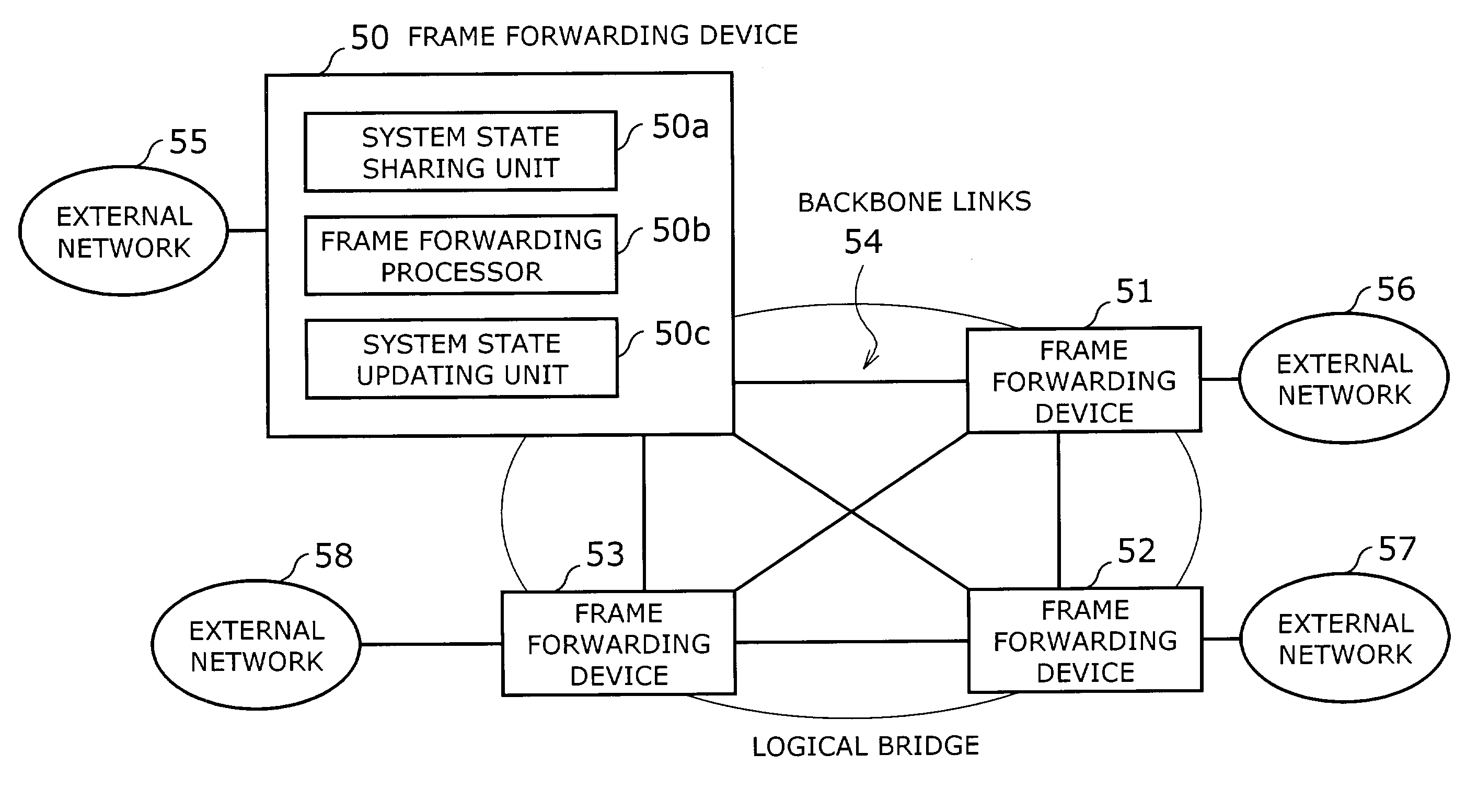
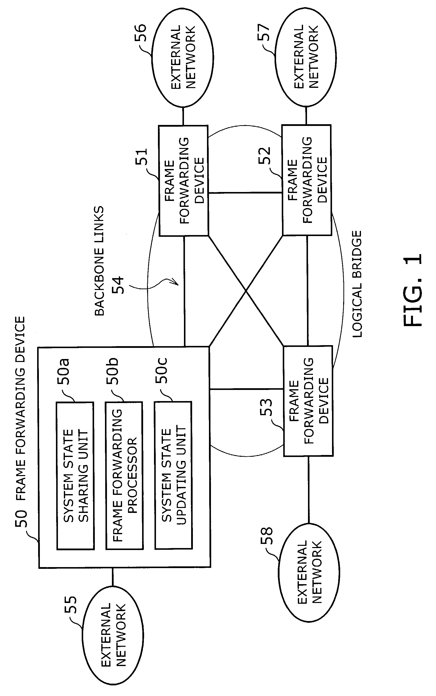
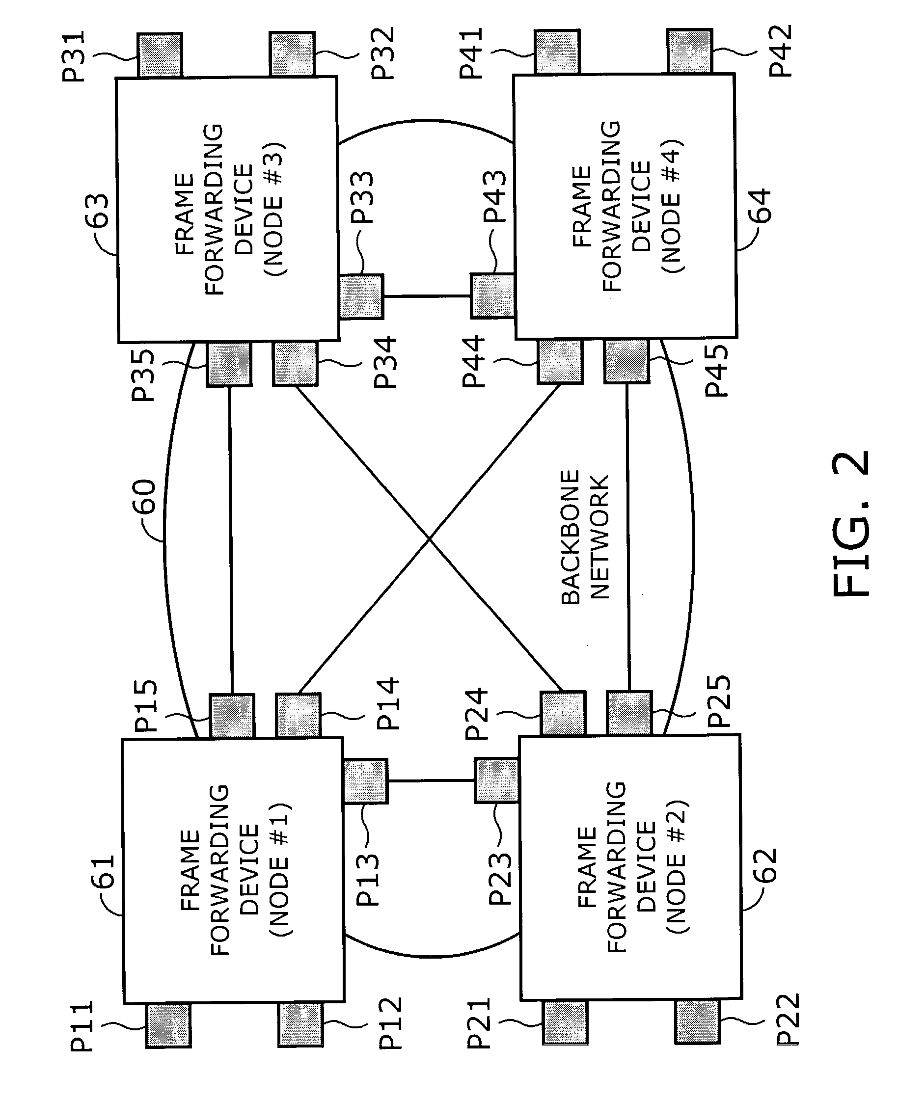
[0077]Referring now to FIG. 2, a frame forwarding system according to the present invention will be described below. FIG. 2 is a block diagram of a frame forwarding system, which involves a plurality of nodes, or frame forwarding devices 61 to 64, and a backbone network 60 interconnecting them. The backbone network 60 conveys packets between external networks that belong to a particular group, and the frame forwarding devices 61 to 64 have packet forwarding functions and spanning tree algorithm processing functions.

[0078]The edge nodes in the illustrated system have physical or logical ports to send and receive data frames to / from external networks (not shown). These ports are referred to as “external network ports,” and their individual port state is managed by the spanning tree algorithm. The remaining ports, on the other hand, are called “inter-node connection ports,” which are used to transfer data frames from one node to another within a logical bridge. That is, data frames rec...

second embodiment

[0168]According to the invention, the frame forwarding device 81 operates as follows. When an STP BPDU is received on an external network port P11 or P12, the BPDU sharing protocol processor 81e extracts network topology configuration data from the received STP BPDU and forwards that data to other nodes, as well as sending it the spanning tree algorithm processor 81c. This is accomplished by identifying particular inter-node connection ports associated with the receiving external network port, and then forwarding the received STP BPDU on those ports, with the assistance of the inter-node communication processor 81f.

[0169]The outgoing inter-node connection port mapping table of FIG. 20 aids the BPDU sharing protocol processor 81e to do the above task. More specifically, BPDUs received on an external network port P11 (i.e., logical bridge port LP1) are forwarded out inter-node connection ports P13, P15, and P17. Similarly, BPDUs received on another external network port P12 (i.e., LP...

third embodiment

[0220]The following gives a more detailed description of how the third embodiment makes the system of FIG. 22 work as a single logical bridge. In the proposed system, the server 105 is supposed to manage the logical bridge configuration, and to this end, it employs a spanning tree algorithm processor 105d. Upon receipt of a BPDU from an external network, the receiving node forwards it out an inter-node connection port to the server 105. Since the receiving inter-node connection port is known, the server 105 can identify the logical bridge port on which the BPDU was received, consulting the table shown in FIG. 25. This permits the external network port manager 105e to update its database, which includes a change in the state of a specific logical bridge port on a node. The server 105 now sends a port control message to that node, requesting it to change its bridge port state. The backbone network 100 functions as an internal bus in the logical bridge, which provides paths for transpo...


PUM


Abstract

A frame forwarding system which has a plurality of frame forwarding devices and links to transport frames between external networks that belong to a particular group. This system is designed to prevent backbone links from being blocked even when there is a backdoor link that forms a potential loop in the network. A system state sharing unit in a frame forwarding device shares system state information with other frame forwarding devices. This information sharing enables all the frame forwarding devices and inter-node links to behave as a single virtual device for forwarding frames between external networks that belong to a particular group. A frame forwarding processor forwards received frames according to the system state information shared among all the frame forwarding devices in the system.

Description

BACKGROUND OF THE INVENTION[0001]1. Field of the Invention[0002]The present invention relates to a device, network, and system for forwarding frames between geographically dispersed user networks. More particularly, the present invention relates to a frame forwarding system which employs a plurality of devices and links to transport frames between external user networks that belong to a particular group. The present invention also relates to the devices and network involved in that system.[0003]2. Description of the Related Art[0004]Many companies have an enterprise network for communication between their geographically dispersed business units through the use of wide area network (WAN) connections. To support construction of such networks, Internet service providers and telecommunications carriers (collectively, WAN providers) are offering virtual private network (VPN) services on their backbone network, permitting a group of external user networks to use a part of the bandwidth of...

Claims


Application Information

Patent Timeline
Patent Type & Authority Patents(United States)
IPC IPC(8): H04L12/28H04L12/46H04L45/18
CPCH04L45/18H04L45/04
Inventor OGUCHI, NAOKI
Owner FUJITSU LTD
Why Eureka
Try Eureka