
Image forming apparatus, image processing method, program, and image processing apparatus

a technology of image processing and forming apparatus, applied in the field of image processing apparatus, can solve the problems of reducing image quality, reducing color reproducibility, and unable to render normal printing, and achieve the effect of improving color reproducibility

Inactive Publication Date: 2009-09-29
SEIKO EPSON CORP
View PDF4 Cites 4 Cited by
  • Summary
  • Abstract
  • Description
  • Claims
  • Application Information

AI Technical Summary

Benefits of technology

The solution effectively prevents blurring and improves color reproducibility in dark areas by dynamically controlling toner amounts, avoiding brightness inversion and maintaining high image quality across varying toner levels.

Problems solved by technology

In this case, although color representation is possible up to a Duty of 400% in which toners in all four colors (recording agent) are mixed at 100%, when data with such a high Duty are printed, the print paper winds around the fusing unit due to the large amount of toner, thereby rendering normal printing impossible.
Further, a drop in image quality also results when printing is performed such that so-called blurring caused by the scattering of toner, is generated, and therefore fine lines and the like run.
In addition, there is a risk of the recording medium absorbing ink when data with this high Duty is printed.
However, the generation of blurring due to the type of printer cannot be prevented by means of undercolor removal and black generation alone, and a drop in image quality cannot be prevented unless the Duty of the whole amount of toner in four colors is reduced to about 150%, for example.
Meanwhile, when the Duty is limited (to about 150%, for example) in a single uniform fashion, because brightness inversion is generated in dark areas and the color reproduction range is then small, deterioration in the picture quality results.

Method used


Image

  • Image forming apparatus, image processing method, program, and image processing apparatus
  • Image forming apparatus, image processing method, program, and image processing apparatus
  • Image forming apparatus, image processing method, program, and image processing apparatus

Examples


Embodiment Construction

[0029]Embodiments of the present invention will be described below with reference to the drawings.

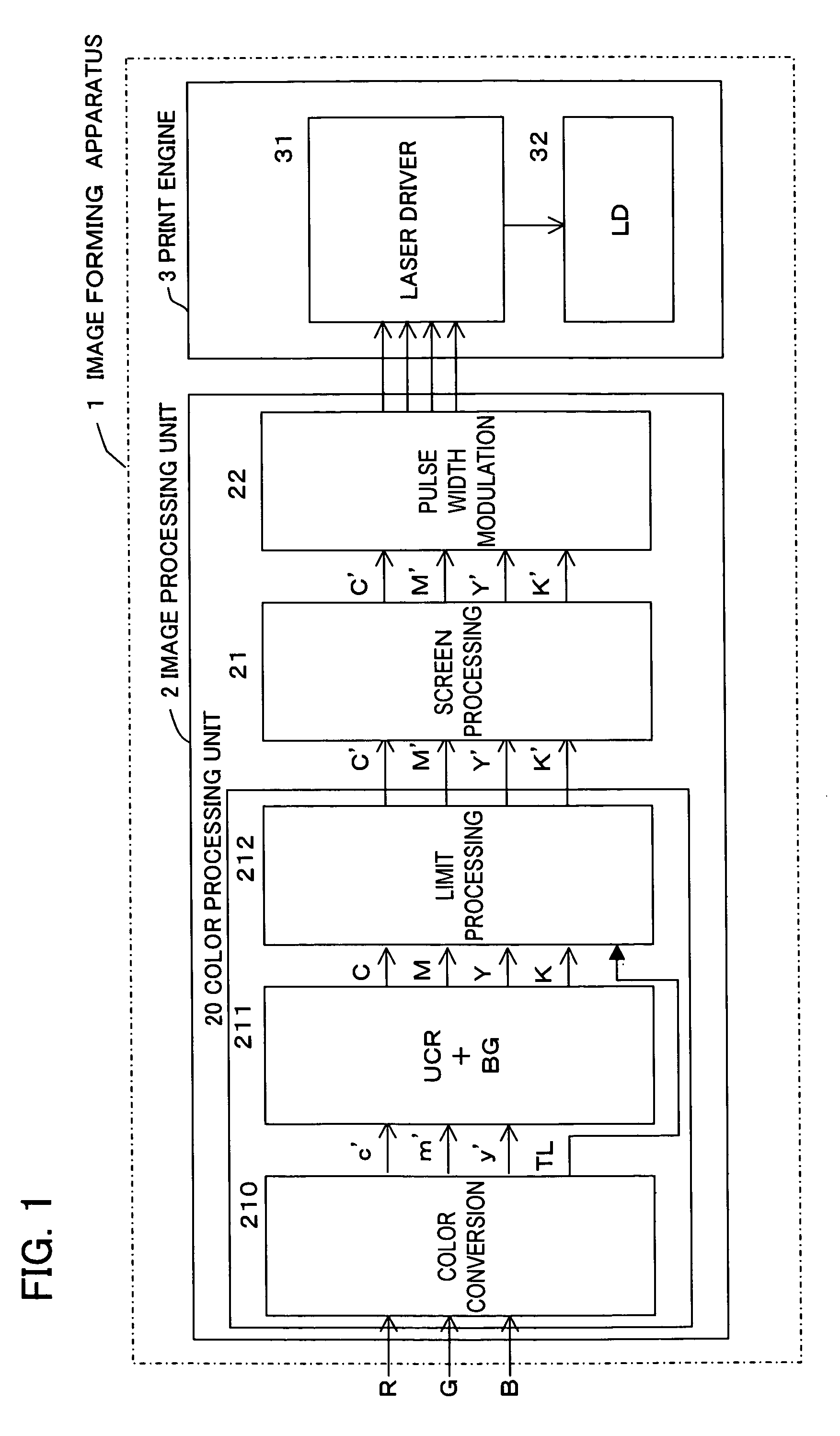
[0030]FIG. 1 shows the constitution of an image forming apparatus 1 to which the present invention is applied. The image forming apparatus 1 is constituted overall by an image processing unit 2 and a print engine 3. The image processing unit 2 is constituted by a color processing unit 20 that performs processing such as color conversion, a screen processing unit 21, and a pulse width modulation unit 22. The print engine 3 is constituted by a laser driver 31 and a laser diode (LD) 32. In addition, the color processing unit 20 is constituted by a color conversion unit 210, a UCR+BG unit 211 for performing undercolor removal processing or similar, and a limit processing unit 212 that performs Duty limitation by means of a largest limit amount.

[0031]An outline of the operation of the image forming apparatus 1 will be described next. First, RGB data are inputted to the image forming apparatu...


PUM


Abstract

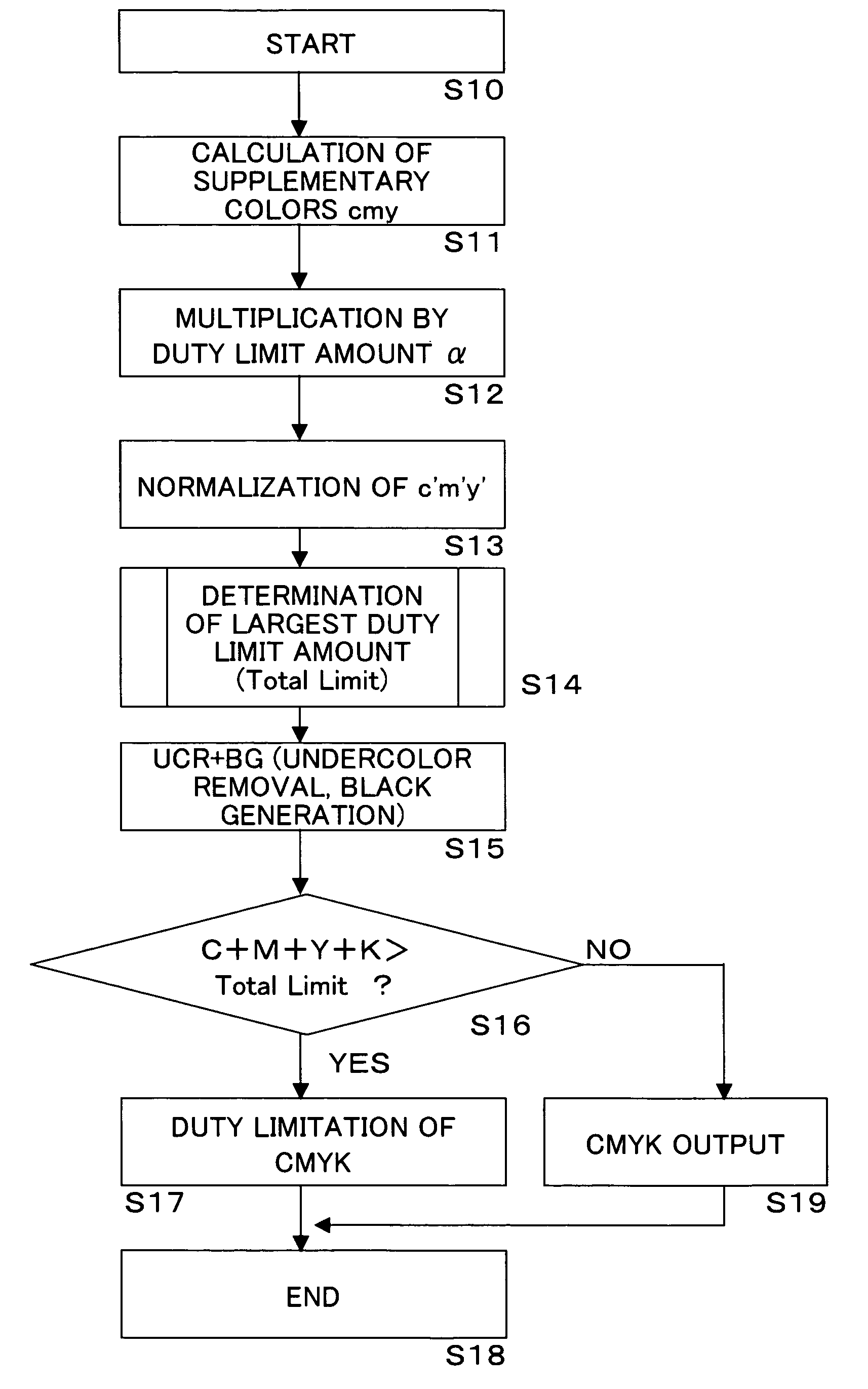
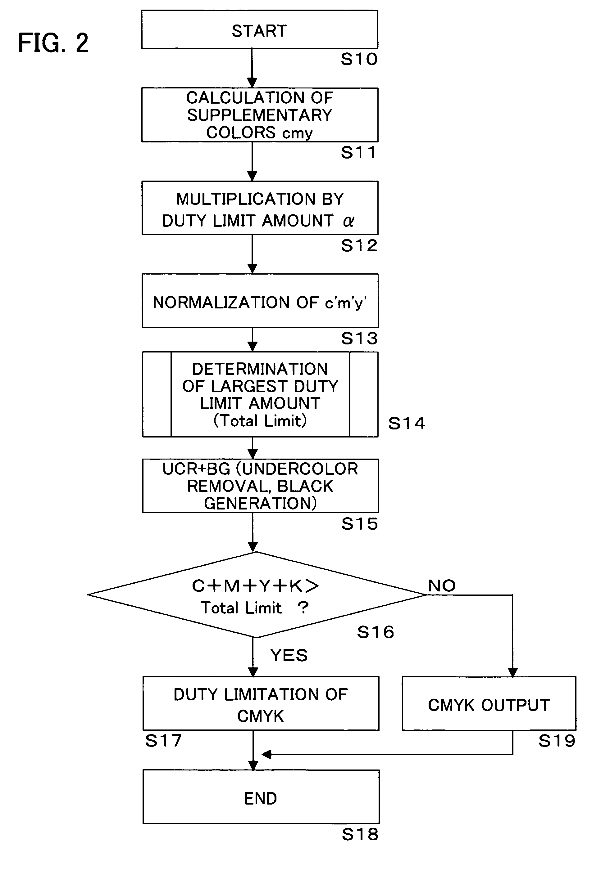
c, m, and y, which are the primary colors, are calculated from inputted RGB data. Duty limitation is then applied to c, m, and y by means of the limit amount α. c′, m′, and y′, which have been limited by α, are then normalized. The largest limit amount is β when the normalized values are less than 200%. If these values are between 200% and 250%, β+((c″+m″+y″) / 255−2)×2γ is then the largest limit amount, which is β+γ when the values are equal to or more than 250%. C, M, Y, and K are obtained by subjecting c′, m′, and y′ to under color removal and black generation processing. Unless the total of these values exceeds the largest limit amount, C, M, Y, K are outputted as is as the output values C′, M′, Y′, and K′. When the largest limit amount is exceeded, Duty limitation is applied.

Description

BACKGROUND OF THE INVENTION[0001]1. Field of the Invention[0002]The present invention relates to an image forming apparatus and method thereof, and, more particularly, to an image forming apparatus that limits the amounts of toner of a plurality of colors, and the method thereof.[0003]2. Description of the Related Art[0004]When a color printer generates an image, color representation is normally performed by means of toner, ink, and so forth in four colors, which are cyan (C), magenta (M), yellow (Y), and black (K). In this case, although color representation is possible up to a Duty of 400% in which toners in all four colors (recording agent) are mixed at 100%, when data with such a high Duty are printed, the print paper winds around the fusing unit due to the large amount of toner, thereby rendering normal printing impossible. Further, a drop in image quality also results when printing is performed such that so-called blurring caused by the scattering of toner, is generated, and t...

Claims


Application Information

Patent Timeline
Patent Type & Authority Patents(United States)
IPC IPC(8): G06K9/00B41J2/525G06T1/00G06T5/00H04N1/46H04N1/60
CPCH04N1/6022H04N1/60
Inventor KOBAYASHI
Owner SEIKO EPSON CORP
Learn More