
Diamagnetic levitation system

a diamagnetic levitation and noncontact technology, applied in the direction of acceleration measurement in multiple dimensions, acceleration measurement using interia forces, instruments, etc., can solve the problems of inability to achieve stable levitation in the axial direction, limit all those inertial sensing systems, and sometimes critical power consumption of such systems

Inactive Publication Date: 2009-10-06
ECOLE POLYTECHNIQUE FEDERALE DE LAUSANNE (EPFL)
View PDF8 Cites 15 Cited by
  • Summary
  • Abstract
  • Description
  • Claims
  • Application Information

AI Technical Summary

Benefits of technology

This approach eliminates friction-related issues and reduces energy consumption, providing highly sensitive and accurate inertial measurements while maintaining the diamagnetic element in a stable, non-contact position, suitable for various inertial sensing applications.

Problems solved by technology

The limitation of all those inertial sensing systems is mainly due to friction between the inertial mass and the base of the instrument.
Indeed this friction is responsible for imprecise measurement, of wear between the mechanical parts in contact, and it might also lead to failure due to mechanical fatigue.
In addition inertial sensing systems, such as seismometers in seismology or inclinometers in civil engineering, are often placed to monitor structures or machines and the power consumption of such systems is sometimes a critical factor.
The diamagnetic force exerted over the inertial mass is created by a 1D arrangement of large horseshoe magnets resulting in an unstable levitation in the axial direction.
In such a configuration magnets are heavier than graphite for the same volume of material, and diamagnetic materials (such as pyrolitic graphite) is much more expensive than magnets for the same volume of material (or for the same weight).

Method used


Image

  • Diamagnetic levitation system
  • Diamagnetic levitation system
  • Diamagnetic levitation system

Examples


Embodiment Construction

[0078]Several kinds of precision instruments can be designed on the principle of a diamagnetic material levitated over a 2D array of permanent magnets and kept in a precise position with electrostatic actuation.

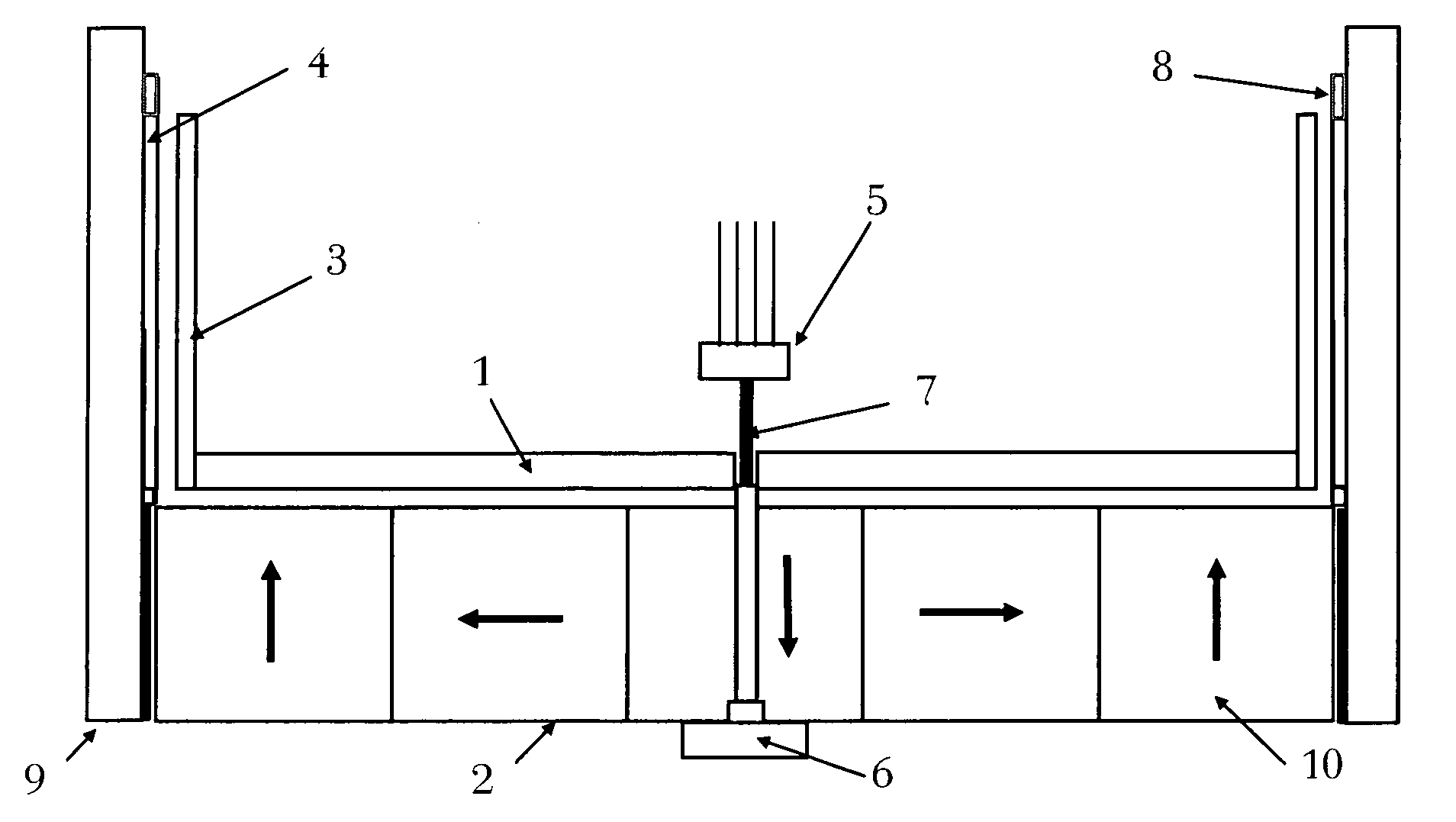
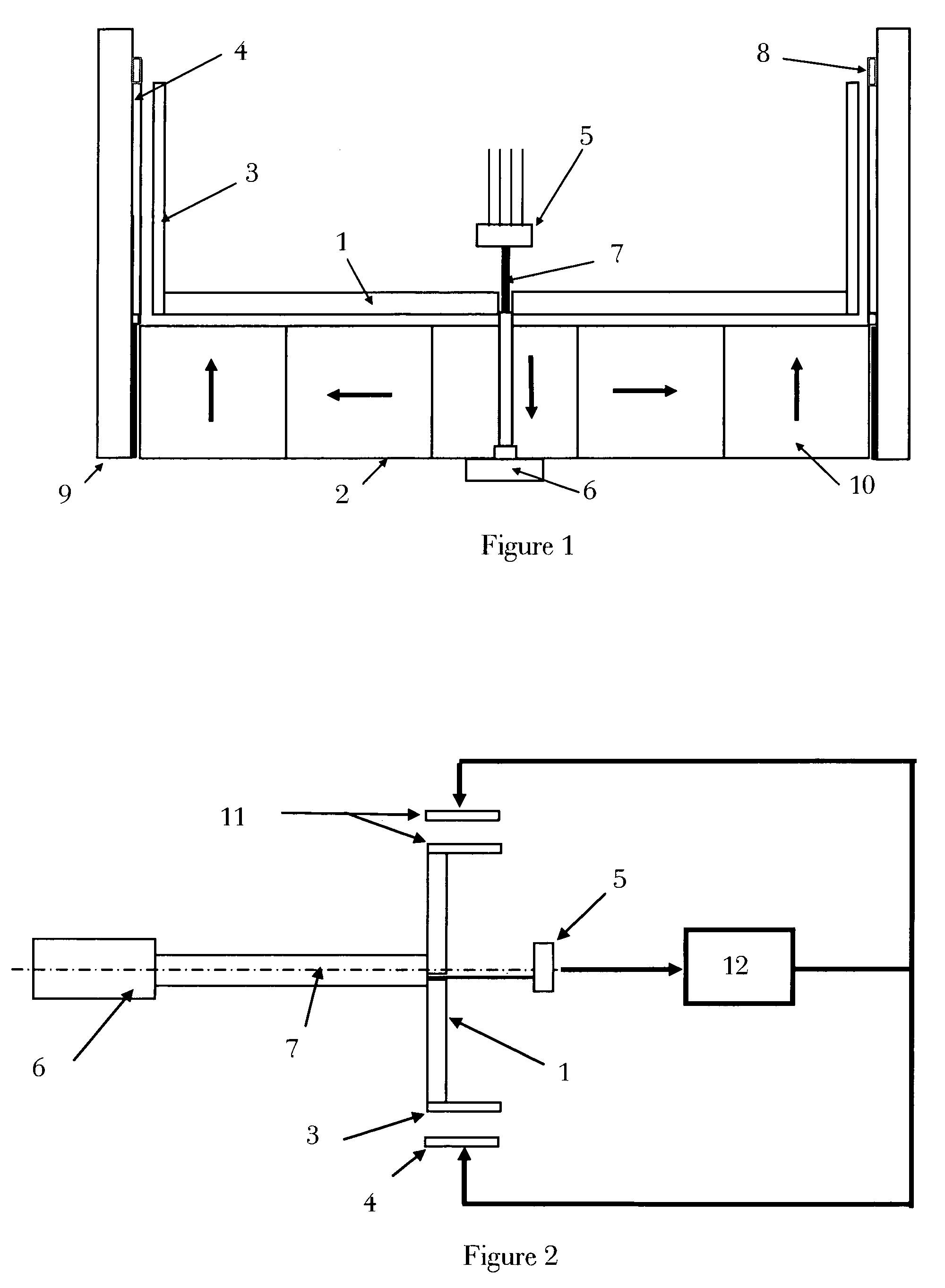
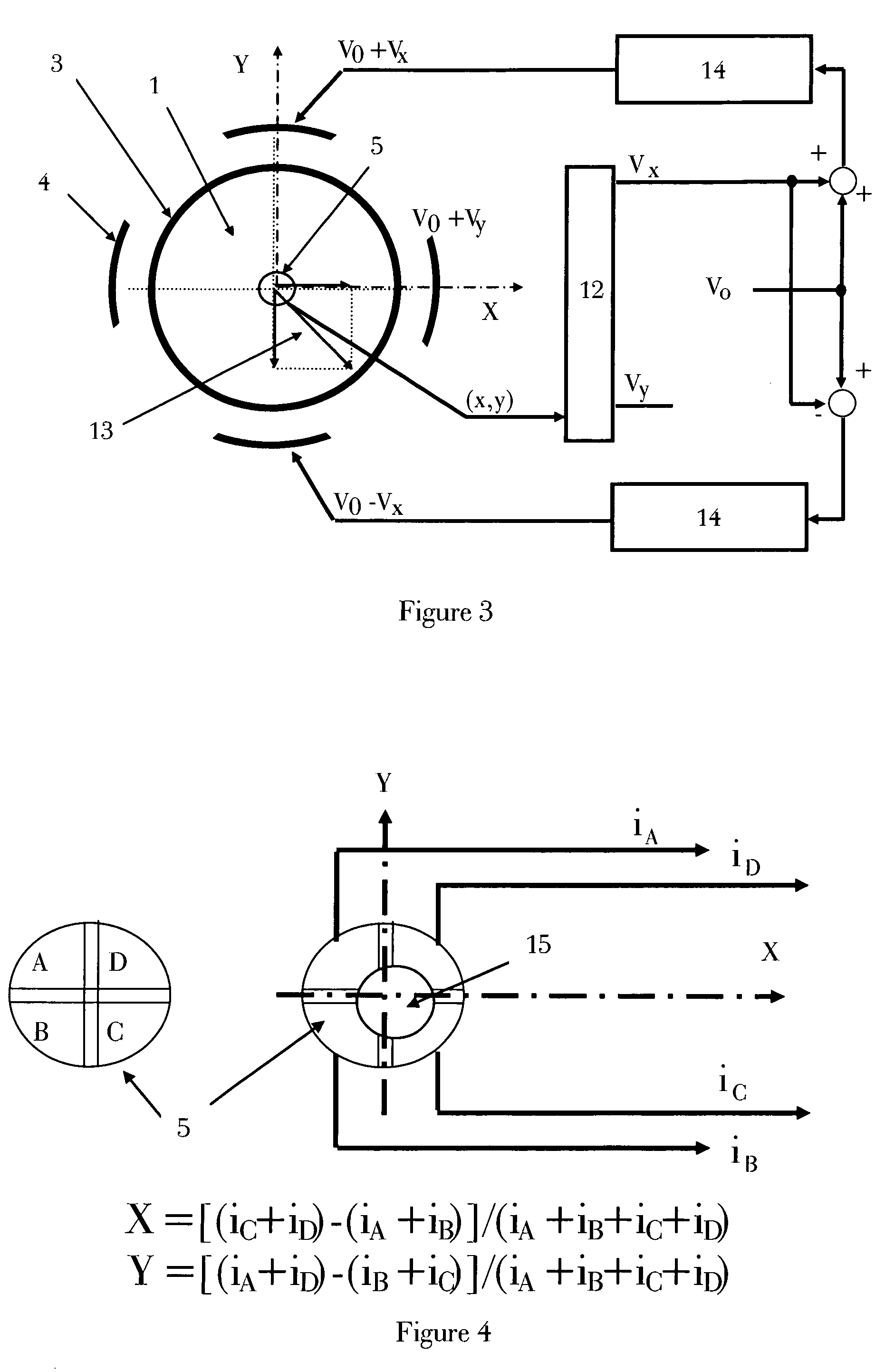
[0079]We will describe a preferred embodiment (cf FIG. 1, FIG. 2, FIG. 3, FIG. 4, FIG. 7) that can be used as:[0080]A bidirectional acceleration sensor or a bi-directional seismometer[0081]A bi-directional tiltmeter (inclinometer)[0082]A gyroscope with the addition of an alternating voltage applied on comb electrodes 20 and 21 (FIG. 11) instead of the plain electrodes 4 (or 4′ and 4″).[0083]A bidirectional actuator.[0084]A gravimeter.

[0085]In the preferred embodiment described in FIG. 1, FIG. 2, FIG. 3, FIG. 4, and FIG. 7, a diamagnetic disc 1 is surrounded with a cylindrical aluminum crown 3 and is levitated over a Halbach-2D array 2 (cf. FIG. 13.f) of permanent magnets 10.

[0086]The position of the disc 1 is controlled in a feed-back loop.

[0087]This feed-back loop is made of...


PUM


Abstract

The invention concerns an inertial sensor or an actuator based on diamagnetic levitation, said inertial sensor or actuator comprising support means serving as main support body for an inertial sensor or for an actuator, a two dimensional array of permanent magnets and a diamagnetic element facing the said array characterized in that said diamagnetic material constitutes the inertial mass or the moving part of the actuator.

Description

[0001]This application is the US national phase of international application PCT / CH2003 / 000596 filed 2 Sep. 2003 which designated the U.S. and claims benefit of PCT / CH02 / 00480, dated 2 Sep. 2002, the entire content of which is hereby incorporated by reference.FIELD OF THE INVENTION[0002]The present invention relates to non-contact systems based on diamagnetic levitation.BACKGROUND OF THE INVENTION[0003]Current inertial sensing systems such as accelerometers, gravimeters and inclinometers are based on the relative displacement between an inertial mass and the base of the instrument when the base is subject to an external perturbation (vibration, modification of the “g” level, angle); and gyroscopes, which are another kind of inertial sensing system, are made of an inertial mass which is rotated about one of its axes of inertia and the measurement relies on the relative movement between the axis and the base of the instrument, or on the force generated by the axis on the base of the i...

Claims


Application Information

Patent Timeline
Patent Type & Authority Patents(United States)
IPC IPC(8): G01P15/16G01C9/06F16C39/06G01C9/00G01C9/10G01C19/08G01C19/24G01P15/02G01P15/093G01P15/13G01P15/18G01V1/18G01V7/00
CPCF16C32/0436F16C32/0444F16C39/063G01C9/06G01C9/10G01V7/00G01P15/093G01P15/131G01P15/18G01V1/181G01C19/24
Inventor MOSER, ROLANDSANDTNER, JANBARROT, FRANCOIS
Owner ECOLE POLYTECHNIQUE FEDERALE DE LAUSANNE (EPFL)
Learn More