Micro range radio frequency (RF) communications link

a radio frequency and communications link technology, applied in the field of communications links, can solve the problems of cable damage, installation, maintenance and troubleshooting, and significant overhead for installation, maintenance and troubleshooting, and achieve the effect of removing interferen

Inactive Publication Date: 2009-10-06
HONEYWELL INT INC
View PDF9 Cites 75 Cited by
  • Summary
  • Abstract
  • Description
  • Claims
  • Application Information

AI Technical Summary

Benefits of technology

[0010]Applicant has developed a micro range RF communications link that is used to transmit data from a moving device to an access point or a receiver positioned along a fixed path of motion of the moving device. Each receiver includes a shield that can channel or funnel the transmitted data signal to the receiver to overcome the drawbacks of the prior art by eliminating any interference caused by overlapping radio signal.
[0012]The micro range RF data transmission system further includes at least one receiver incorporated into the moving device and at least one transmitter positioned along the fixed path. Each transmitter(s) is positioned along the fixed path such that when the at least one receiver in the moving device is proximate to each transmitter(s), each of the one of the at least one receiver in the moving device aligns with one of the at least one transmitter creating a reverse data transfer point. The data transfer point and the reverse data transfer point allow for a simultaneous bi-directional data transfer between the fixed path and the moving device.

Problems solved by technology

However, the use of cables causes a significant overhead for installation, maintenance and troubleshooting.
For example, several of the machine parts are in a difficult location to attach a cable or replace the cable that requires a significant cost for the installation and maintenance.
Additionally, as the machine is used, the cables become damaged and must be replaced.
Further, network routing would require significant overhead and / or a separate device dedicated to control routing communication signals between devices.
Additionally, even if only a small section of the cable is damaged, the entire cable will be replaced.
However, the uncoordinated transmission of wireless signals leads to signal interference.
However, an industrial environment is very noisy and is rampant with interference by electromechanical devices in the area.
Additionally, wireless devices transmitting RF signals in the same area contribute to transmission failures.

Method used


Image

  • Micro range radio frequency (RF) communications link
  • Micro range radio frequency (RF) communications link
  • Micro range radio frequency (RF) communications link

Examples


second embodiment

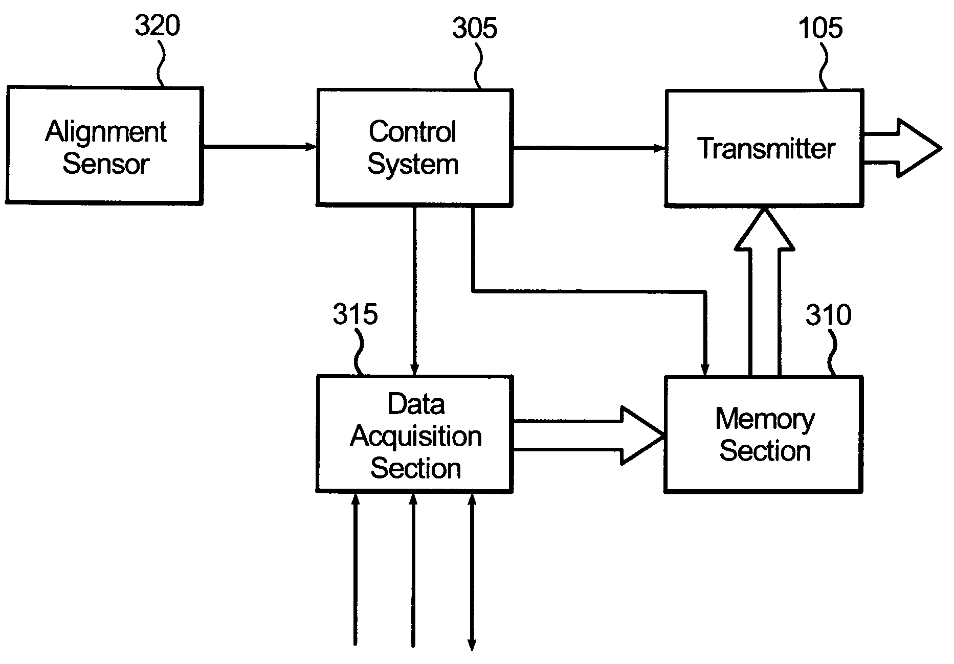
[0036] the moving device 100 includes both at least one transmitter 405 and at least one receiver 410. The at least one transmitter 405 and at least one receiver 410 is positioned within the moving device 100 to align with a receiver and transmitter, respectively, located on the path of motion 110, as will be described later.

first embodiment

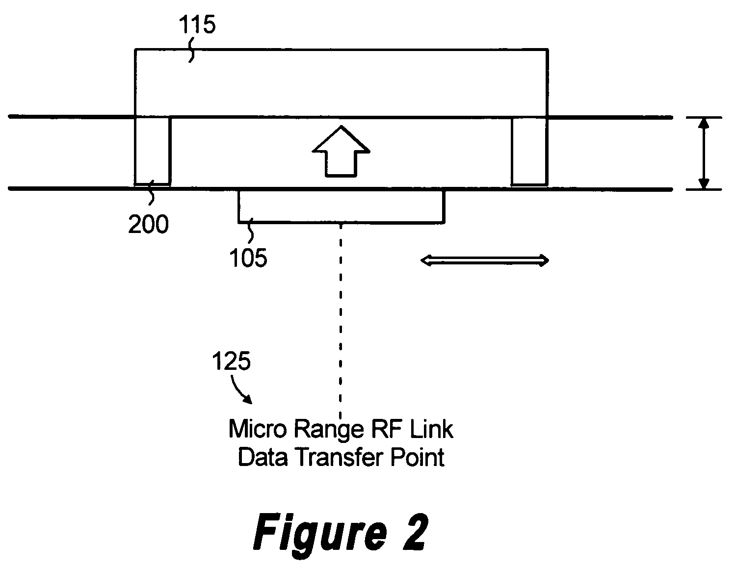
[0037]Similar to receiver 115, each receiver 410 will have an electromagnetic shield 200 formed at the perimeter or circumference of the receiver 410. The electromagnetic shield 200 is similar to the electromagnetic shield 200 as set forth above with respect to the first embodiment and, therefore, will not be described again. The path of motion 110 includes at least one transmitter 425 and receiver 430. All receivers 430 will include the electromagnetic shield 200. Each receiver 430 and transmitter 425 combination creates a transmission pair 435 and is positioned proximate to each other to facilitate simultaneous transmission with the receiver 410 and the transmitter 405. Each transmission pair 435 is positioned along the path of motion 110 such that the pair can be simultaneously aligned with the moving device's receiver 410 and transmitter 405. When the moving device's receiver 410 and transmitter 405 are aligned with or in a defined proximate distance with the transmission pair 4...


PUM


Abstract

A micro range RF data transmission system comprising at least one transmitter incorporated in a moving device and at least one receiver positioned along a fixed path that can be aligned to create a data transfer point. The moving device moves along a fixed path. Each of the at least one receiver is positioned along the fixed path such that when the moving device moves along the fixed path, one of the transmitters aligns with one of the receivers creating the data transfer point. The transmitter will only transmit a micro range signal when the transmitter is at the data transfer point. Each receiver includes an electromagnetic shield formed around the perimeter of the receiver to form a directional channel for the micro range signal. A control system is used for controlling an industrial sheet-making device. The control system uses multiple data transfer points as the backbone for bi-directional communication.

Description

CROSS REFERENCE TO RELATED APPLICATION[0001]The present application claims priority from U.S. Provisional Application No. 60 / 755,628 filed on Dec. 30, 2005.BACKGROUND OF THE INVENTION[0002]1. Field of Invention[0003]The invention relates to a communications link and more particularly to a micro range RF communications link between a moving device and at least one access point positioned along a predefined path of motion for the moving device.[0004]2. Description of Related Art[0005]Data communication between various parts or components of an industrial machine or between a plurality of industrial devices is integral to a control and management system for industrial manufacturing. As a result, the type of communications link becomes extremely important. Factors that are considered when selecting a type of communications link are data transmission rate, range, battery life, security, cost, quality of service, and interoperability.[0006]One type of communications links is a wired cable...

Claims


Application Information

Patent Timeline
Patent Type & Authority Patents(United States)
IPC IPC(8): H04B1/38
CPCH04B5/02G06K7/0008
Inventor BIK, TADEUSZ M.
Owner HONEYWELL INT INC
Why Eureka
Try Eureka