
Instrumented ballistic test projectile

Inactive Publication Date: 2009-10-13
UNITED STATES OF AMERICA THE AS REPRESENTED BY THE SEC OF THE ARMY
View PDF11 Cites 20 Cited by
  • Summary
  • Abstract
  • Description
  • Claims
  • Application Information

AI Technical Summary

Problems solved by technology

Additionally, these older devices were one-time shot devices that were destroyed during the test.

Method used


Image

  • Instrumented ballistic test projectile
  • Instrumented ballistic test projectile
  • Instrumented ballistic test projectile

Examples


Embodiment Construction

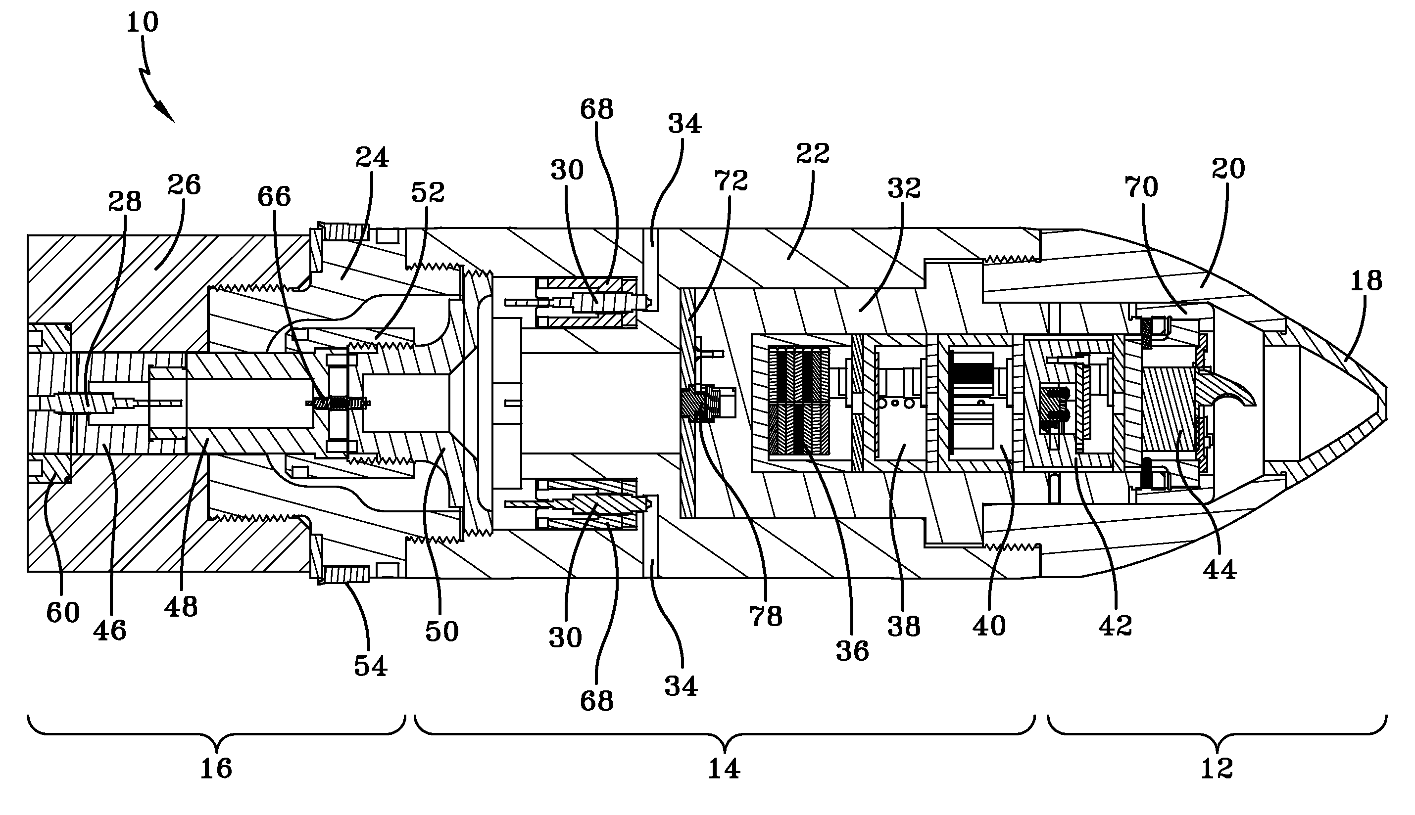
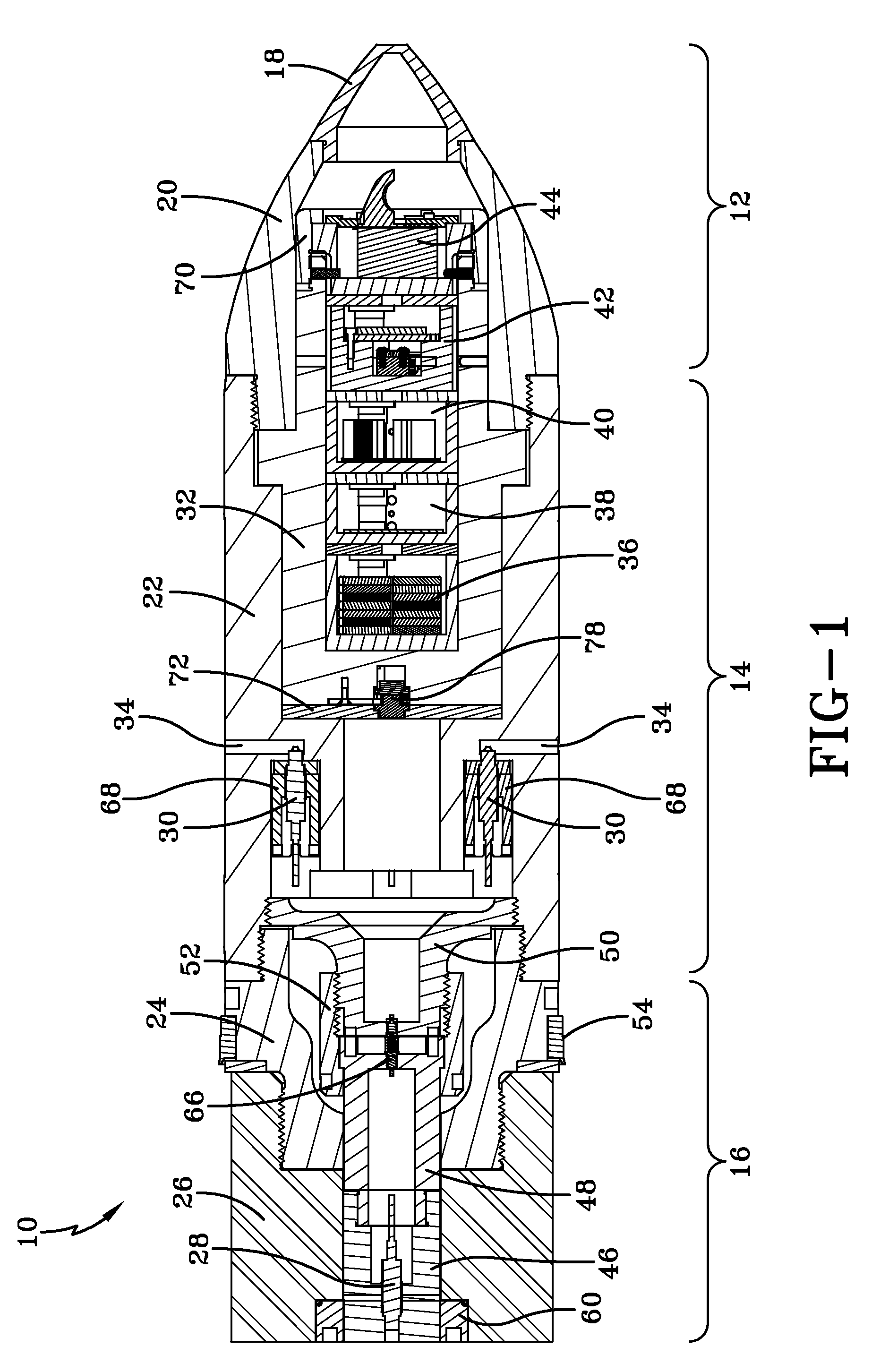
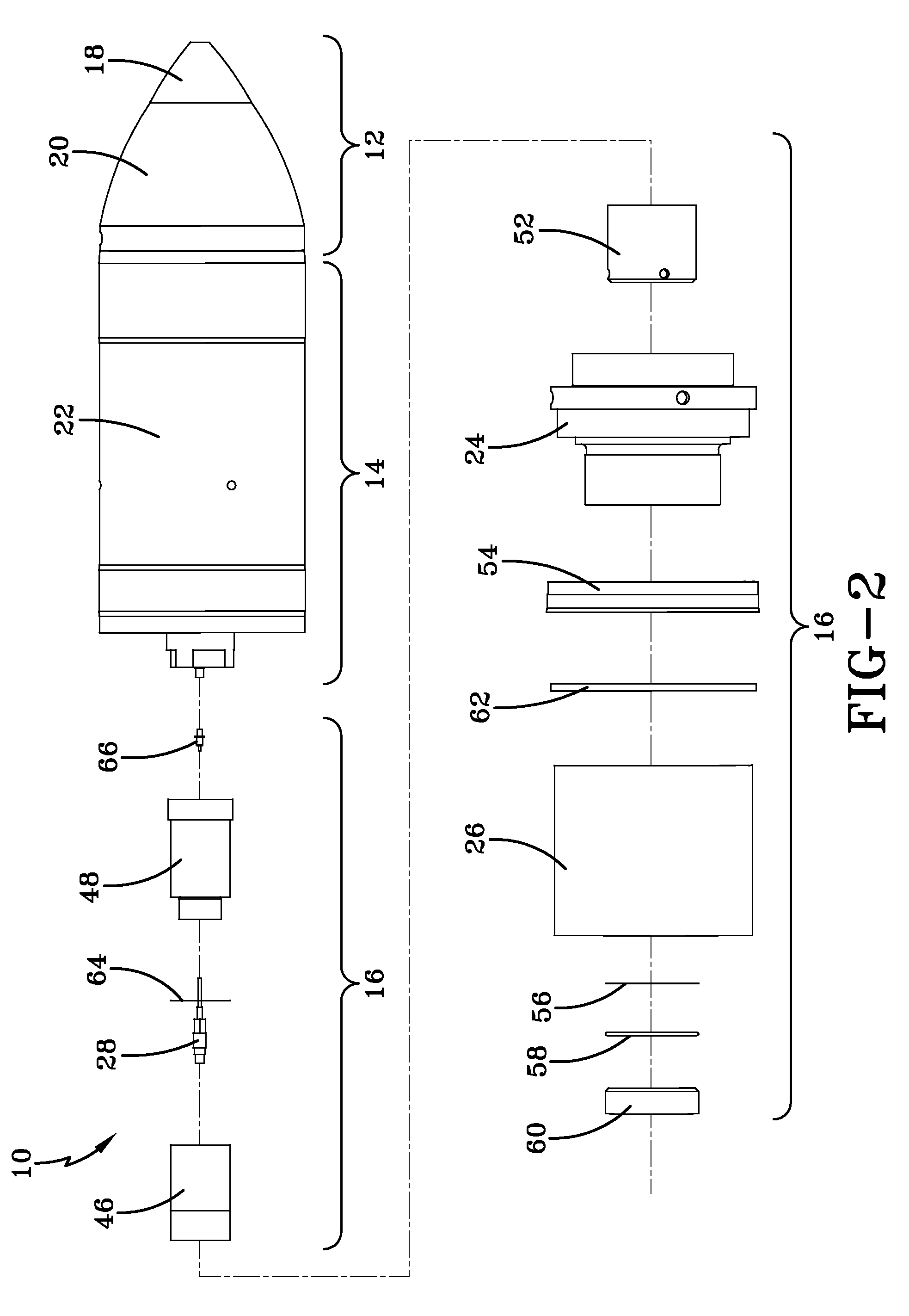
[0016]The invention comprises a projectile that senses and transmits the interior ballistic event in realtime. The primary interest is in conditions inside the launch tube, however, the projectile may also be used to measure and transmit data once the projectile has exited the launch tube. The projectile may be launched from a cannon tube or mortar tube, for example. The instrumented ballistic test projectile is rugged enough so that most of its components are reusable, with limited refurbishment. The present invention withstands the high acceleration and spin rate of the cannon launching environment.

[0017]A combined telemetry and sensor system and hardened projectile body allow the capture of the pressurized environment on the base and side of the projectile as it is being launched. A tri-axial accelerometer module senses the acceleration forces in all three linear directions. The signals from the sensors are combined and transmitted at an extremely high rate so as not to degrade t...


PUM

PropertyMeasurementUnit
stabilityaaaaaaaaaa
velocityaaaaaaaaaa
pressureaaaaaaaaaa

Abstract

A ballistic test projectile includes a nose section comprising a windshield and aft of the windshield, an ogive; a body section aft of the nose section, the body section comprising a generally cylindrical body connected to the ogive; a base section aft of the body section, the base section comprising a base adapter connected to the body and a base bottom connected to the base adapter; a base pressure gage disposed in the base bottom; at least one side pressure gage disposed in the body; and an electronics cup disposed in the body, the electronics cup comprising a battery cup, a signal conditioning cup, a multiplexer cup, an accelerometer cup and a transmitter cup.

Description

STATEMENT OF GOVERNMENT INTEREST[0001]The inventions described herein may be manufactured, used and licensed by or for the U.S. Government for U.S. Government purposes.BACKGROUND OF THE INVENTION[0002]The invention relates in general to ballistic munitions and in particular to ballistic projectiles that measure conditions in the launching tube.[0003]Military organizations have always needed a device to obtain information about the interior ballistic environment of cannon launching projectiles. Knowledge of launching conditions is used to design cannons and munitions to achieve optimum launching and accuracy. Only within the past 50 years have scientists started placing sensors into projectiles to record the interior ballistic event. Early electronic devices were pressure sensors that were hard-wired to a data acquisition system located near the cannon. When the projectile was launched, the data acquisition system would record several milliseconds of data before the wire was broken.[...

Claims


Application Information

Patent Timeline
Patent Type & Authority Patents(United States)
IPC IPC(8): G01L5/14
CPCF42B12/365F42B35/00F42B30/006F42B15/08
Inventor HOLLIS, MICHAELHAWKSWELL, MATTHEWST OURS, ROGERCARLUCCI, DONALDFLYASH, BORIS
Owner UNITED STATES OF AMERICA THE AS REPRESENTED BY THE SEC OF THE ARMY
Learn More