Sealing collar

a sealing collar and sealing lip technology, applied in the field of sealing collars, can solve the problems of reducing the sealing effect reducing the strength of the sealing lip, and not being able to facilitate mounting, etc., and achieves the effect of reducing the friction coefficien

Inactive Publication Date: 2009-10-13
CONTINENTAL TEVES AG & CO OHG
View PDF17 Cites 5 Cited by
  • Summary
  • Abstract
  • Description
  • Claims
  • Application Information

AI Technical Summary

Benefits of technology

[0010]A special advantage of the invention involves that the statically applied sealing lip can have a very elastical design because it no longer has to ensure that the dynamically applied sealing lip is kept at a distance from the slot between the surfaces to be sealed. Therefore, the second sealing lip is preferably configured such that it can be passed over by pressure fluid flow and hence provides the effect of a valve. As regards the dynamically stressed sealing lip this is possible within limits only because this sealing lip must have a relatively robust design.
[0011]To maintain sufficient stiffness of the extension, the strength of the extension as a difference between inside and outside diameter has at least the same rate as the strength of each of the sealing lips. This imparts a comparative strength also to the back of the sealing collar so that the sealing lips can generate the necessary radial preload.
[0012]As explained hereinabove, the sealing collar of the invention is especially appropriate because it not only seals a pressurized space but additionally is in a position to act as a valve when the direction of the pressure is reversed. However, because the end surface of the extension abuts on the radial groove wall during fluid overflow, the end area at the free end of the extension is provided with radial apertures according to a favorable aspect of the invention, said apertures allowing pressure fluid to pass through in a radial direction. It can be achieved this way that the pressure fluid flowing basically via the statically stressed sealing lip can flow off in a radially inward direction in the area of the groove wall. These apertures may e.g. be bores extending radially through the extension.
[0013]Manufacture can be simplified because the apertures in the extension are open in an axial direction towards the free end of the extension. The extension indicated hereinabove as being circumferential will then be decomposed into single extensions being placed on a circumferential circle preferably at an equal distance from each other, the free ends of said extensions being supported on the groove wall. Usually the supporting members connected to a sealing collar are made of a material that is stiffer compared to the material of the sealing collar.
[0014]A particularly low-cost design is achieved, however, when the extension is integrally connected to the sealing collar and is preferably made of the same material because the collar herein can be made in one single casting operation without coupling two parts.

Problems solved by technology

However, as the inside sealing lip with its free end reaches into the area of the boundary between the cylinder and the piston and these boundaries move relative each other, there is the risk that the end of the sealing lip is squeezed in the slot between cylinder and piston.
It is, however, disadvantageous that such a stiff sealing lip provides a reduced sealing effect and does not lend itself to ease of mounting.

Method used


Image

  • Sealing collar
  • Sealing collar

Examples


Embodiment Construction

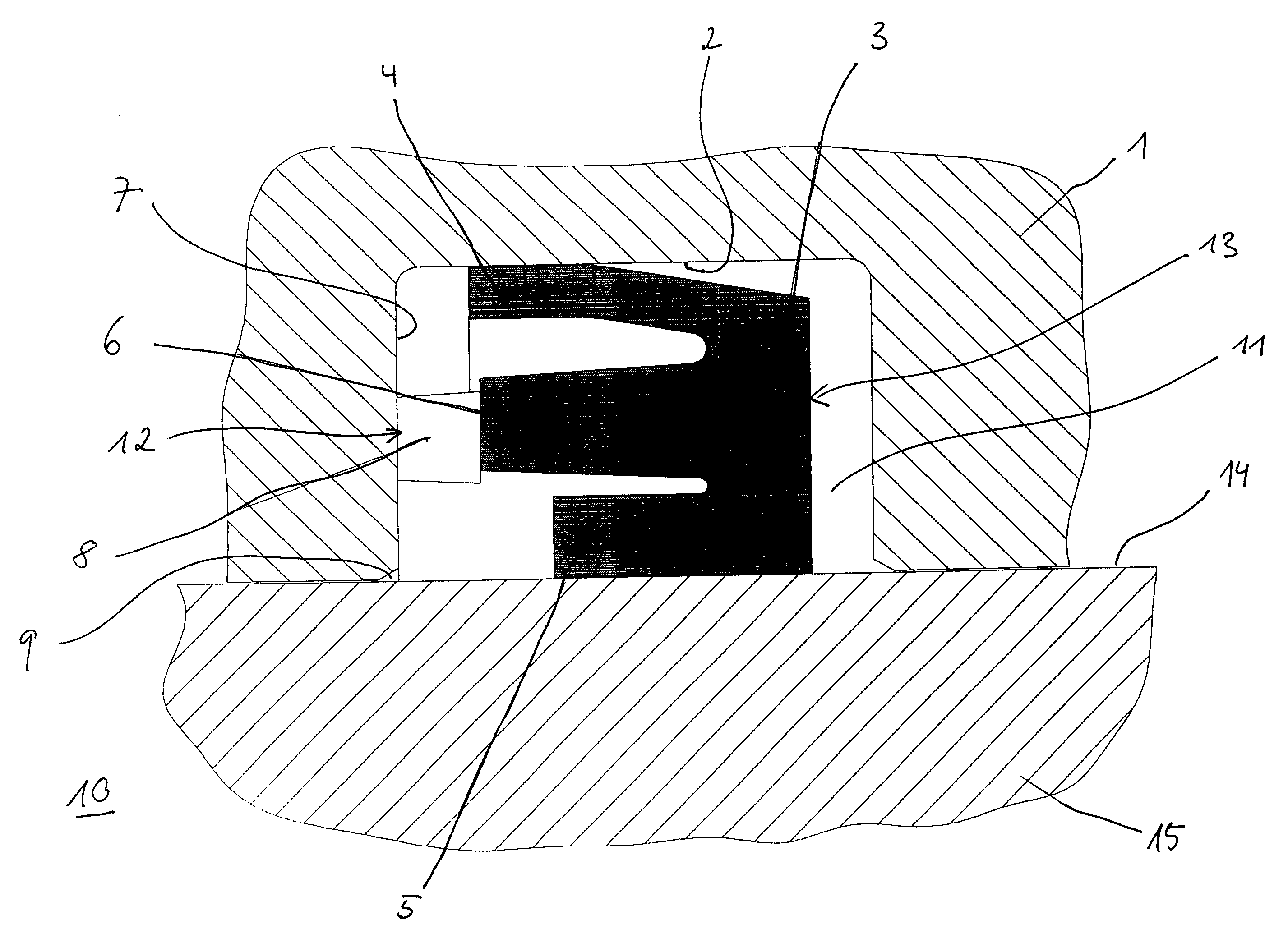
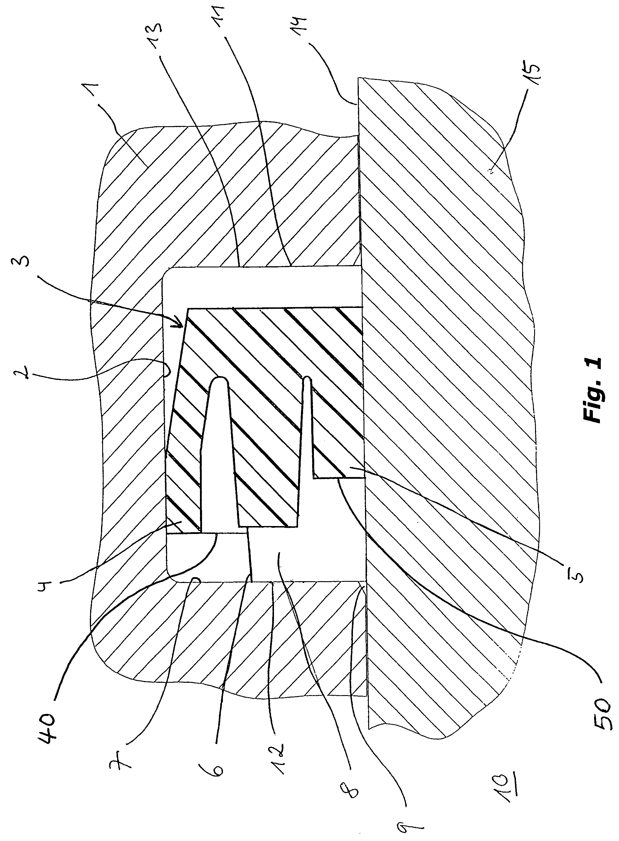
[0017]The drawing shows, in a broken-out and cross-sectional view, a section of the housing of a cylinder 1 of a cylinder-and-piston unit 1, 15, said housing accommodating a sealing collar 3 in a groove 2. Said sealing collar 3 comprises an outside sealing lip 4 disposed radially outwards and an inside sealing lip 5 disposed radially inwards. The outside sealing lip 4 is statically stressed and laterally movable in groove 2 to a small extent only. On the other hand, a peripheral surface 14 of the piston 15, shown in a broken-out fashion, is displaced with respect to the inside sealing lip 5. An extension 6 is arranged radially between the inside sealing lip 5 and the outside sealing lip 4 and abuts with an end surface 12 of its free end on a wall 7 of the groove 2, maintaining the free ends 40, 50 of the two radially offset sealing lips 4, 5 at a distance from the wall 7. The free end of the extension 6 is provided with radial apertures 8 through which pressure fluid can propagate a...


PUM


Abstract

The invention relates to a sealing collar for a cylinder-and-piston unit, wherein the sealing collar is essentially received in a groove that is inserted into the cylinder or the piston, respectively, and the sealing collar comprises two sealing lips, the first sealing lip thereof being acted upon dynamically and making catch at the piston or the cylinder, respectively, while the second sealing lip thereof is acted upon statically and rests on a bottom of the groove.It is the core of the invention that the sealing collar includes a circumferential extension that extends in parallel to the sealing lips, is arranged radially between the first sealing lip and the second sealing lip and projects from the sealing lips in an axial direction.

Description

TECHNICAL FIELD[0001]The present invention relates to a sealing collar for a cylinder-and-piston unit, wherein the sealing collar is essentially received in a groove that is inserted into the cylinder or the piston, respectively, and the sealing collar comprises two sealing lips, the first sealing lip thereof being acted upon dynamically and making catch at the piston or the cylinder, respectively, while the second sealing lip thereof is acted upon statically and rests on the bottom of the groove.[0002]The objective of sealing collars of this type is to seal a working chamber in relation to the ambience, and the sealing collar can be fitted either to the cylinder or to the piston.BACKGROUND OF THE INVENTION[0003]EP 0 889 265 A1 discloses a piston seal including an inside sealing lip and an outside sealing lip, with the inside sealing lip being stressed dynamically, while the outside sealing lip is stressed statically. The outward end of the outside sealing lip projects in an axial d...

Claims


Application Information

Patent Timeline
Patent Type & Authority Patents(United States)
IPC IPC(8): F16J9/20F16J15/16F16J15/32
CPCF16J15/3236F16J15/164
Inventor DROTT, PETERKONIG, HARALDJUNGMANN, UDOBISCHOFF, ANDREASKOPPEL, HANS-MICHAEL
Owner CONTINENTAL TEVES AG & CO OHG
Why Eureka
Try Eureka