Hollow CMC airfoil with internal stitch

a technology of hollow cores and airfoils, which is applied in the direction of liquid fuel engines, marine propulsion, vessel construction, etc., can solve the problems of high stress for a given inner/outer pressure differential, insatiable cmc airfoils, and particularly susceptible to wall bending loads

Inactive Publication Date: 2009-10-13
SIEMENS ENERGY INC
View PDF11 Cites 34 Cited by
  • Summary
  • Abstract
  • Description
  • Claims
  • Application Information

AI Technical Summary

Problems solved by technology

CMC airfoils with hollow cores in gas turbines are particularly susceptible to wall bending loads associated with such pressure differentials due to the anisotropic strength behavior of CMC material.
This problem is accentuated in large airfoils with long chord length, such as those used in large land-based gas turbines.
A longer internal chamber size results in increased bending moments on the walls of the airfoil, resulting in higher stresses for a given inner / outer pressure differential.
However this is not fully satisfactory for CMC airfoils, due to manufacturing constraints and also due to thermal radial expansion stress that builds between the hot airfoil skin and the cooler spars.

Method used


Image

  • Hollow CMC airfoil with internal stitch
  • Hollow CMC airfoil with internal stitch
  • Hollow CMC airfoil with internal stitch

Examples


Embodiment Construction

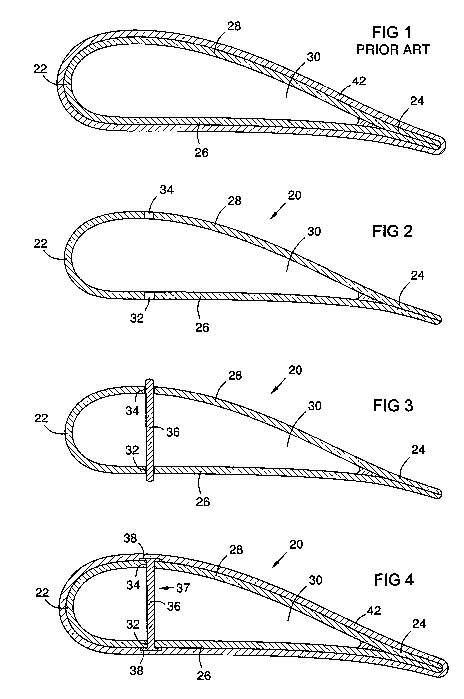
[0016]FIG. 1 shows a sectional view of a prior art hollow CMC airfoil formed with walls made of a ceramic fabric infused with a ceramic matrix. The airfoil has a leading edge 22, a trailing edge 24, a pressure wall 26, a suction wall 28, and an interior space 30. It may also have an insulative outer layer 42. High-temperature insulation for ceramic matrix composites has been described in U.S. Pat. No. 6,197,424, incorporated by reference herein, which issued on Mar. 6, 2001, and is commonly assigned with the present invention.

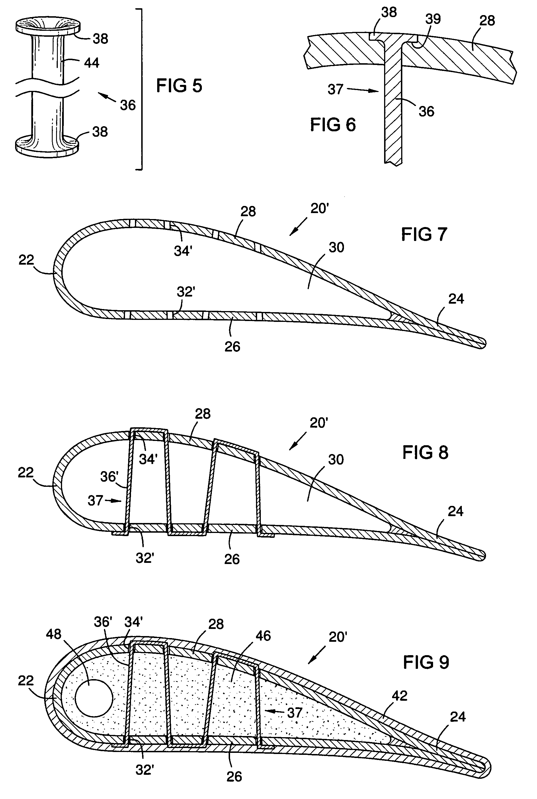
[0017]FIG. 2 shows a CMC airfoil 20 with holes 32 and 34 formed in the pressure and suction walls 26, 28. The holes 32, 34 may be formed by any known technique, for example laser drilling, after drying or partially to fully curing the CMC walls 26, 28. FIG. 3 shows a bundle of ceramic fibers 36 passing through the holes 32 and 34. FIG. 4 shows the bundle of ceramic fibers 36 flared 38 at both ends against outer surfaces of the walls 26, 28. The bundle of cerami...


PUM

PropertyMeasurementUnit
pressureaaaaaaaaaa
shrinkageaaaaaaaaaa
aspect ratioaaaaaaaaaa

Abstract

A CMC airfoil (20) formed with CMC stitches (37) interconnected between opposed walls (26, 28) of the airfoil to restrain outward flexing of the walls resulting from pressurized cooling air within the airfoil. The airfoil may be formed of a ceramic fabric infused with a ceramic matrix and dried, and may be partially to fully cured. Then holes (32, 34) are formed in the opposed walls of the airfoil, and a ceramic stitching element such as ceramic fibers (36) or a ceramic tube (44) is threaded through the holes. The stitching element is infused with a wet ceramic matrix before or after threading, and is flared (38) or otherwise anchored to the walls (26, 28) to form a stitch (37) there between. The airfoil and stitch are then cured. If the airfoil is cured before stitching, a pre-tension is formed in the stitch due to relative curing shrinkage.

Description

FIELD OF THE INVENTION[0001]The invention relates to ceramic matrix composite (CMC) fabrication technology for airfoils that are internally cooled with compressed air, such as turbine blades and vanes in gas turbine engines.BACKGROUND OF THE INVENTION[0002]Design requirements for internally cooled airfoils necessitate a positive pressure differential between the internal cooling air and the external hot gas environment to prevent hot gas intrusion into the airfoil in the event of an airfoil wall breach. CMC airfoils with hollow cores in gas turbines are particularly susceptible to wall bending loads associated with such pressure differentials due to the anisotropic strength behavior of CMC material. For laminate CMC constructions, the through-thickness direction has about 5% of the strength of the in-plane or fiber-direction strengths. Internal cooling air pressure causes high interlaminar tensile stresses in a hollow CMC airfoil, with maximum stress concentrations typically occurri...

Claims


Application Information

Patent Timeline
Patent Type & Authority Patents(United States)
IPC IPC(8): F01D5/18
CPCF01D5/147F01D5/187F01D5/284F01D5/282F05D2300/603F05D2300/21
Inventor VANCE, STEVEN J.MORRISON, JAY A.
Owner SIEMENS ENERGY INC
Why Eureka
Try Eureka