Gas-liquid separator utilizing turning vanes to capture liquid droplets as well as redirect the gas flow around a bend

a gas-liquid separator and vanes technology, applied in the direction of separation process, liquid degasification, filtration separation, etc., can solve the problems of high energy consumption, severe pressure drop, and loss of valuable reactants of liquid droplets

Active Publication Date: 2009-10-13
ALPEK POLYESTER SA DE CV
View PDF22 Cites 4 Cited by
  • Summary
  • Abstract
  • Description
  • Claims
  • Application Information

AI Technical Summary

Problems solved by technology

However, in other processes, considerable quantities of liquid droplets may be associated with the gas phase, and in the case where the liquid droplets can later solidify, whether due strictly to a phase change or to subsequent reaction, lines and valves may be plugged and require disassembly and cleaning or replacement.
Furthermore, in many cases, the liquid droplets may constitute a loss of valuable reactants, intermediate products, or end products.
However, many of these methods, for instance chill plates, are energy intensive, and others such as packed columns exhibit a severe pressure drop as well as being prone to plugging.
In-line filters also suffer from these drawbacks.
However, such separators are generally efficient only for droplets of materials with large inertia.
Since in many cases the separator must be maintained at a specific operating temperature and thus requires considerable external insulation, such devices are relatively capital intensive.
This device is of rather complex construction, and is believed to be useable only when configured for horizontal flow due to the placement of liquid-trapping baffles and drains.
Moreover, conversion of linear flow to a swirling flow necessarily requires energy, which is manifested as a pressure drop.
Use of a rinsing liquid is undesirable in many applications.
The fishbone construction described in the '998 patent is limited in that it is placed in the upstream (inlet) region of an elbow where the centerline of the elbow inlet is substantially vertical.
This limitation is significant in that the conduit system carrying the gas exiting polymerization reactors tend to be large and inflexible offering only a limited number of available conduit positions for placing the gas-liquid separator.

Method used


Image

  • Gas-liquid separator utilizing turning vanes to capture liquid droplets as well as redirect the gas flow around a bend
  • Gas-liquid separator utilizing turning vanes to capture liquid droplets as well as redirect the gas flow around a bend
  • Gas-liquid separator utilizing turning vanes to capture liquid droplets as well as redirect the gas flow around a bend

Examples


Embodiment Construction

)

[0032]Reference will now be made in detail to presently preferred compositions or embodiments and methods of the invention, which constitute the best modes of practicing the invention presently known to the inventors.

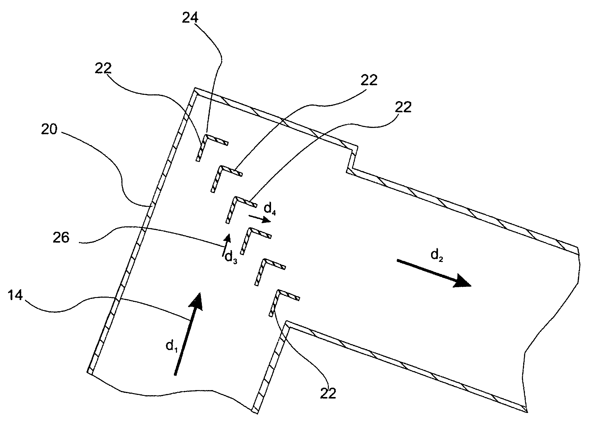
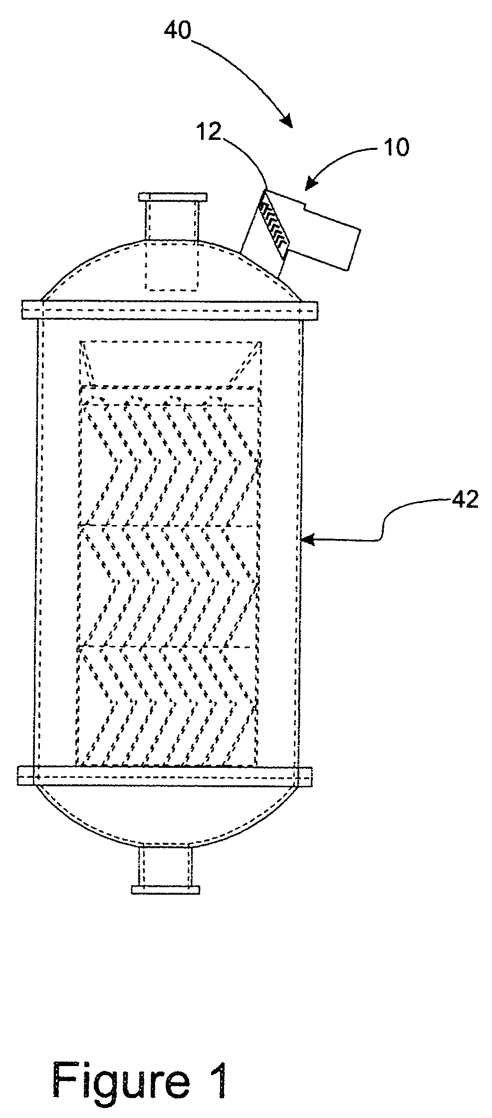
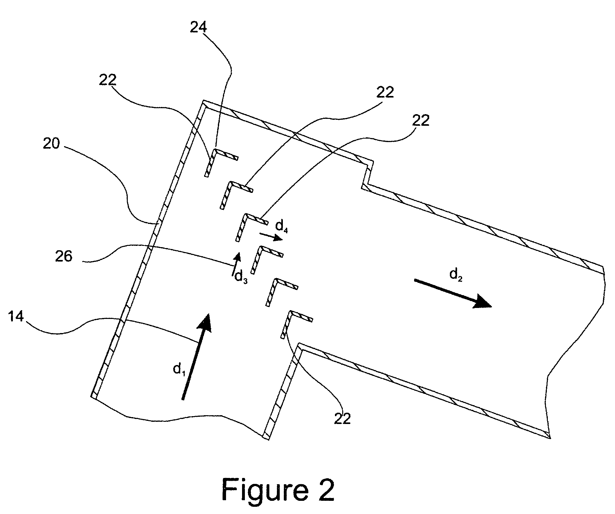
[0033]With reference to FIGS. 1, 2, 3A, and 3B, schematic illustrations of an embodiment of the gas-liquid separation enhancer of the present invention are provided. FIG. 1 is a schematic illustration of a reactor with a gas takeoff incorporating the gas-liquid separation enhancer of the invention. FIG. 2 is a cross-sectional view of a conduit section incorporating the gas-liquid separation enhancer. FIG. 3A is a cross-sectional view of a turning vane used in an embodiment of the gas-liquid separation enhancer of the invention. FIG. 3B is a perspective view of a turning vane used in an embodiment of the gas-liquid separation enhancer of the invention. The gas-liquid separation enhancer of the present embodiment is advantageously used to separate a liquid from a flowing...


PUM

PropertyMeasurementUnit
diameteraaaaaaaaaa
radius of curvatureaaaaaaaaaa
angleaaaaaaaaaa

Abstract

A gas-liquid separation enhancer includes a plurality of longitudinally extending turning vanes distributed within a bent conduit section. At least a portion of the vanes have a bend that redirects a portion of a flowing gas stream from an initial direction to a final direction. Each of the vanes have a first end and a second end and are positioned in the bent conduit section to direct a portion of any liquid contacting the vanes to either the first end or the second end when the gas-liquid separation enhancer is incorporated into an outlet conduit. The separation is positioned in an outlet conduit such that captured liquid droplets are returned to the vessel from which they originate.

Description

CROSS-REFERENCE TO RELATED APPLICATIONS[0001]This application is related to U.S. Pat. No. 7,004,998, issued Sep. 17, 2003 and to U.S. patent application Ser. No. 11 / 155,756 filed Jun. 17, 2005.BACKGROUND OF THE INVENTION[0002]1. Field of the Invention[0003]The present invention is directed to separation of liquid droplets from gas-liquid streams in chemical processes.[0004]2. Background Art[0005]Many chemical processes require take-off of a gas phase from chemical processing equipment such as chemical reactors. In some cases, the nature of the various reactants, products, and by-products facilitate removal of a gas phase substantially free of liquid. However, in other processes, considerable quantities of liquid droplets may be associated with the gas phase, and in the case where the liquid droplets can later solidify, whether due strictly to a phase change or to subsequent reaction, lines and valves may be plugged and require disassembly and cleaning or replacement. Furthermore, in...

Claims


Application Information

Patent Timeline
Patent Type & Authority Patents(United States)
IPC IPC(8): B01D45/08
CPCB01D45/08B01D45/06
Inventor SCHERRER, PAUL KEITH
Owner ALPEK POLYESTER SA DE CV
Why Eureka
Try Eureka