Digital image with reduced object motion blur

a technology of object motion blur and digital image, which is applied in the field of digital image with reduced object motion blur, can solve the problems of reducing image capture, reducing image capture, and reducing light loss, so as to reduce object motion blur and reduce image loss

Inactive Publication Date: 2009-10-13
APPLE INC
View PDF13 Cites 26 Cited by
  • Summary
  • Abstract
  • Description
  • Claims
  • Application Information

AI Technical Summary

Benefits of technology

[0015]An advantage of the present invention is that images with reduced object motion blur can be produced with basic changes to the image processing software without having to use a photographic flash or long exposure times to properly expose a single image.
[0016]A further advantage of the present invention is that images with reduced image capture device-induced blur can be produced in still images without the need for costly special lenses with laterally moveable lens elements.

Problems solved by technology

Much of the light is lost when passing through the optical path of the electronic imaging system.
Typically, about 5% of the light is lost due to lens reflections and haze and about 60% is lost because of the color filter array.
If objects in the scene are moving during capture, a longer exposure time may result in an image with object motion blur.
This method under-exposes the electronic image sensor during image capture so dark images are generated.
An analog or digital gain can be applied to the image signal to brighten the dark images, but those skilled in the art will recognize that this will result in noisy images.
High-grade optical elements with large apertures, which can gather more light and preserve more light passing through them, are therefore not practicable.
A disadvantage of this approach is that the extrapolated pixel values, of an object that is already in motion when the exposure begins, are highly uncertain.
The image brightness, as seen by the sensor, never has a constant value and, therefore, the uncertainty in the extrapolated pixel values results in an image with motion artifacts.
Another disadvantage is that it uses specialized hardware so it cannot be used with the conventional electronic image sensors that are used in current commercial cameras.

Method used


Image

  • Digital image with reduced object motion blur
  • Digital image with reduced object motion blur
  • Digital image with reduced object motion blur

Examples


Embodiment Construction

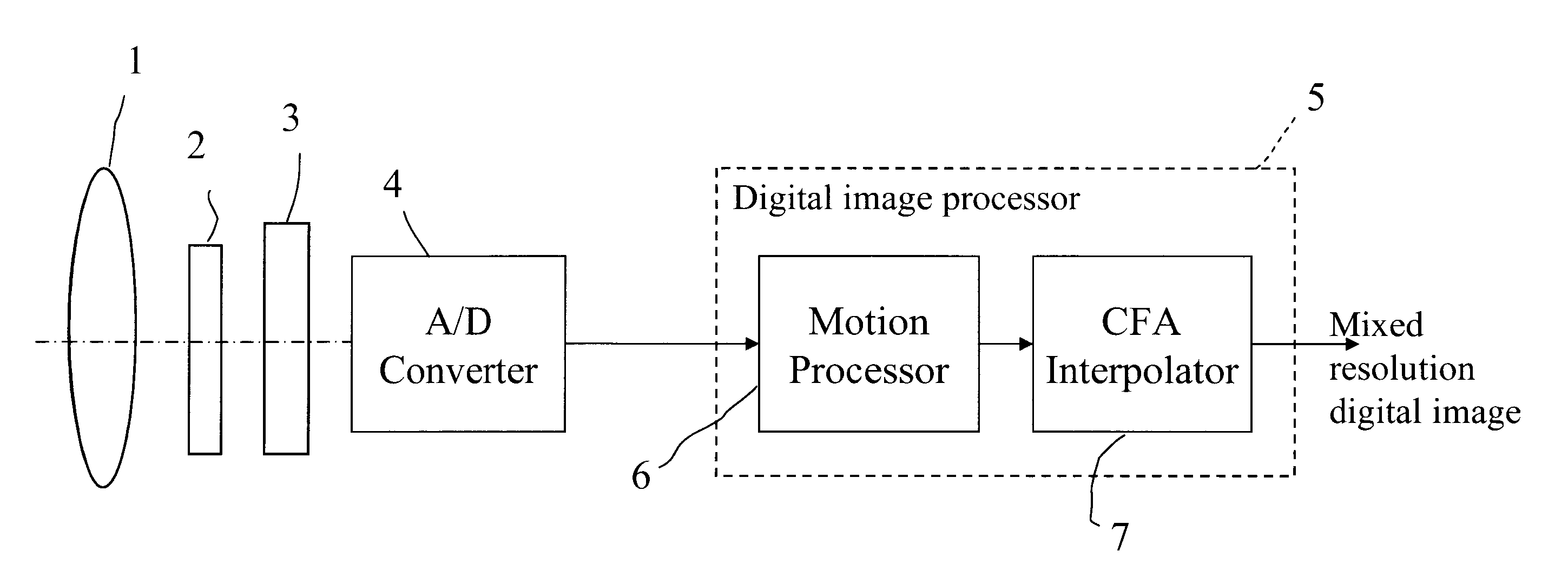
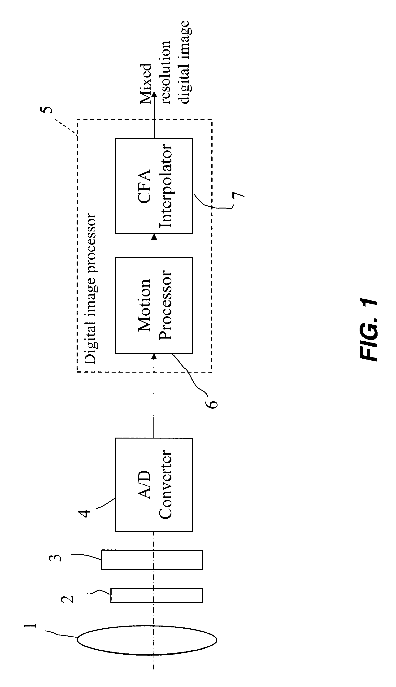
[0022]A digital image includes one or more digital image channels. Each digital image channel includes a two-dimensional array of pixels. Each pixel value relates to the amount of light received by an electronic image sensor corresponding to the geometrical domain of the pixel. For color imaging applications, a digital image will typically consist of red, green, and blue digital image channels. Other configurations, such as using cyan, magenta, and yellow image channels, are also practiced. For monochrome applications, the digital image consists of one digital image channel. Those skilled in the art will recognize that the present invention can be applied to, but is not limited to, a digital image for any of the above-mentioned applications.

[0023]Although the present invention describes a digital image channel as a two-dimensional array of pixel values arranged by rows and columns, those skilled in the art will recognize that the present invention can be applied to mosaic (non-recti...


PUM


Abstract

A method of producing a digital image with reduced object motion blur, includes capturing at least a first and second digital image of a scene using an exposure time that reduces image blur; combining pixels of the first digital image to produce a third digital image which is brighter than the first and second digital images and has a lower resolution than either the first or second digital images; identifying static and moving regions between the first and second digital images; operating on the first and second digital images to produce a fourth digital image which is brighter than the first and second digital images and has object motion blur; and replacing the moving regions in the fourth digital image with corresponding regions from the third digital image to thereby provide a fifth digital image with reduced object motion blur and increased brightness.

Description

FIELD OF THE INVENTION[0001]This invention relates to producing a digital image with reduced object motion blur.BACKGROUND OF THE INVENTION[0002]An electronic imaging system depends on a lens system to form an image on an electronic image sensor to create an electronic representation of a visual image. Examples of such electronic image sensors include charge coupled device (CCD) image sensors and active pixel sensor (APS) devices (APS devices are often referred to as CMOS sensors because of the ability to fabricate them in a Complementary Metal Oxide Semiconductor process). A sensor consists of a two-dimensional array of individual picture element sensors, or pixels. Each pixel is typically provided with either a red, green, or blue filter, as described by Bayer in commonly assigned U.S. Pat. No. 3,971,065 issued Jul. 20, 1976, so that a full color image can be produced. Regardless of electronic technology employed, e.g., CCD or CMOS, the pixel acts as a bucket in which photoelectro...

Claims


Application Information

Patent Timeline
Patent Type & Authority Patents(United States)
IPC IPC(8): H04N5/228
CPCG06T5/50H04N5/23229H04N5/23254H04N5/2327G06T5/003H04N5/23248G06T2207/10144G06T2207/20144G06T2207/20201G06T2207/10024G06T7/194H04N23/6811H04N23/68H04N23/684H04N23/80
Inventor BORDER, JOHN N.MORALES, EFRAIN O.DEEVER, AARON T.
Owner APPLE INC
Why Eureka
Try Eureka