Wiper lever with a driven wiper arm and a wiper blade linked to it for cleaning the windows of motor vehicles in particular

a technology of wiper blades and wiper levers, which is applied in the field of wipers, can solve problems such as unfavorable air stream noise, and achieve the effect of reducing the tolerance for longitudinal dimensions of passage openings and simplifying the assembly of the wiper blade caps

Inactive Publication Date: 2009-10-20
ROBERT BOSCH GMBH
View PDF11 Cites 38 Cited by
  • Summary
  • Abstract
  • Description
  • Claims
  • Application Information

AI Technical Summary

Benefits of technology

[0003]In the case of the wiper lever of the invention, the assembly of the cap on the wiper blade is simplified considerably, because the correct position of the cap is automatically defined due to the arrangement of at least two limit stops pointing in opposite longitudinal directions of the wiper blade, if the cap is provided with co

Problems solved by technology

The gaps thereby yielded between wiper arm and the edge of the passage opening in the cap lead to undesired air stream noise and also interfere with t

Method used


Image

  • Wiper lever with a driven wiper arm and a wiper blade linked to it for cleaning the windows of motor vehicles in particular
  • Wiper lever with a driven wiper arm and a wiper blade linked to it for cleaning the windows of motor vehicles in particular
  • Wiper lever with a driven wiper arm and a wiper blade linked to it for cleaning the windows of motor vehicles in particular

Examples


Embodiment Construction

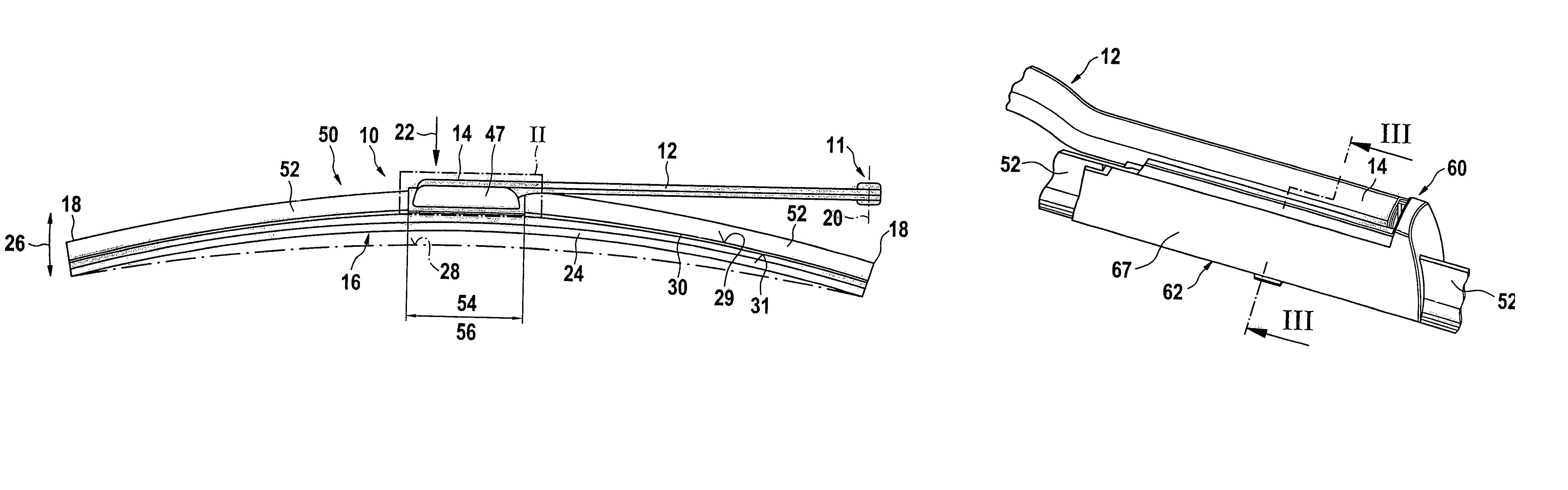
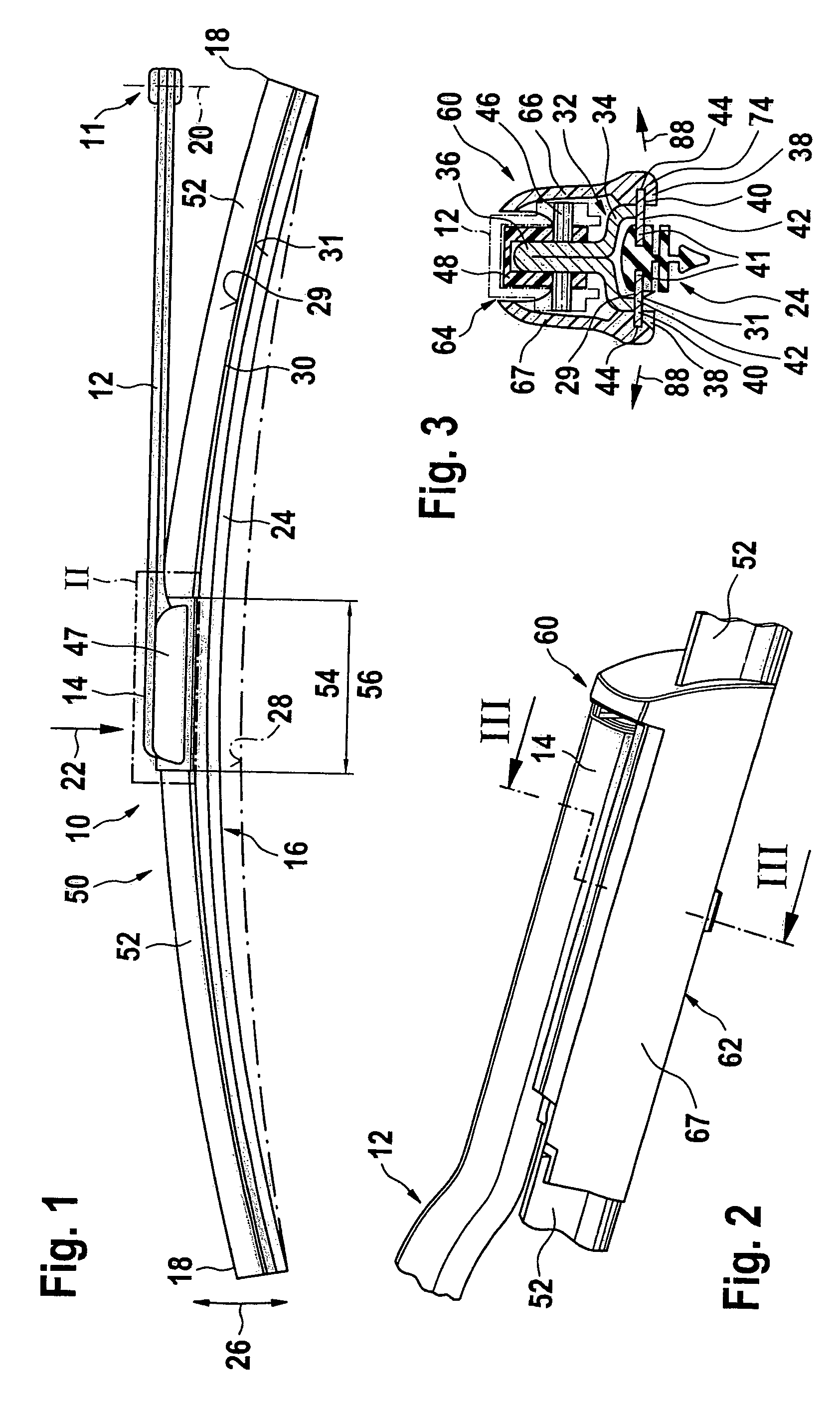
[0017]A driven wiper arm 12 that is guided on one end on a motor vehicle (not shown) is a part of the wiper lever 10 (FIG. 1) in accordance with the invention. The driven end of the wiper arm is provided with reference number 11 in FIG. 1. Linked to the other, free end 14 of the wiper arm is a long-stretched-out wiper blade 16 that belongs to the wiper lever 10. The wiper arm 12 is positioned on its drive end 11 in such a way that, during wiper operation, it can swing back and forth between reverse positions around a pendulum axis 20 in a vertical plane on the drawing plane. In the process, the wiper blade 16 is moved transverse to its longitudinal extension over the to-be-wiped window, whereby it abuts the surface 28 of a to-be-wiped window with a rubber elastic wiper strip 24. The wiper strip 24 is longitudinally axially parallel with a band-like, long-stretched-out, elastic supporting element 30, on whose upper band surface 29 facing away from the window a component 32 sits (FIGS...


PUM

PropertyMeasurementUnit
Distanceaaaaaaaaaa
Elasticityaaaaaaaaaa

Abstract

The invention relates to a wiper lever (10) with a driven wiper arm (12) and a wiper blade (16) linked to it to clean windows, in particular of motor vehicles, which is provided with a band-like, long-stretched-out, elastic supporting element (30) that is curved over its band surfaces, which features a long-stretched-out, rubber elastic wiper strip (24) on its concave curved band surface (31), on whose upper, convex curved band surface (29), in particular in the longitudinal mid-range of the supporting element, a coupling part (32) sits to connect the wiper blade (16) to the wiper arm (12) and wind deflector strip sections (52) extending towards the ends of the supporting element are arranged in particular on both sides of the coupling part and a cap (60) to cover the connecting area between the wiper blade and the wiper arm belongs to the wiper lever, which cap can be locked on the supporting element (30) of the wiper blade and is provided with elastically deflectable locking means (74). Assembly of the cap on the wiper blade in its correct position on the wiper blade is achieved in a simple manner if the supporting element is provided with at least two limit stops (82) each pointing in opposite longitudinal directions of the wiper blade (16) to which corresponding counter limit stops (84) of the cap (60) are assigned.

Description

BACKGROUND OF THE INVENTION[0001]In the case of a known wiper lever, the supporting element of the wiper blade is supposed to guarantee the most uniform possible distribution of wiper blade application force originating from the wiper arm on the window over the entire wiper field being covered by the wiper blade. Because of a corresponding curvature of the unstressed supporting element—i.e., when the wiper blade is not adjacent to the window—the ends of the wiper strip that are applied completely to the window during wiper blade operation are stressed by the then tensioned supporting element on the window, even if the curvature radii of spherically curved vehicle windows change with every wiper blade position. The curvature of the wiper blade must therefore be somewhat greater than the greatest curvature measured in the wiper field on the to-be-wiped window. The supporting element thereby replaces the expensive supporting bracket design, which is required to distribute the applicati...

Claims


Application Information

Patent Timeline
IPC IPC(8): B60S1/40B60S1/38B01D45/18B01D46/00B01D46/10B01D46/24B60S1/34
CPCB60S1/38B60S1/3868B60S1/4064B60S1/40B60S1/3856B60S2001/3843B60S2001/382
Inventor VERELST, HUBERTWINDMOLDERS, ERICWILMS, CHRISTIANBEELEN, HANSVERTONGEN, ROBERT
Owner ROBERT BOSCH GMBH
Why Eureka
Try Eureka