Heat spreader with vapor chamber and method of manufacturing the same

a technology of heat spreader and vapor chamber, which is applied in the direction of indirect heat exchangers, lighting and heating apparatus, etc., can solve the problems of easy modification of the configuration of the heat spreader, and achieve the effects of reducing heat resistance, increasing heat removal capacity of the heat spreader, and simple configuration

Inactive Publication Date: 2009-10-20
HON HAI PRECISION IND CO LTD +1
View PDF12 Cites 6 Cited by
  • Summary
  • Abstract
  • Description
  • Claims
  • Application Information

AI Technical Summary

Benefits of technology

[0008]The present invention relates, in one aspect, to a method for manufacturing a heat spreader. The method for manufacturing a heat spreader includes: providing a core, the core having a mesh including a plurality of pores and a filling material filled in the pores of the mesh and a major space enclosed by the mesh; electrodepositing a layer of metal coating on an outer surface of the core; removing the filling material from the coating layer and the pores of the mesh; and filling a working fluid into the coating layer and hermetically sealing the coating layer to thereby obtain the heat spreader with therein a wick structure formed by the mesh and a vapor chamber formed by said major space. By this method, the heat spreader is easily made to have a complicated configuration. Also, the mesh is integrally formed with the metal casing of the heat spreader as a single piece, which decreases the heat resistance therebetween and thereby increasing heat removal capacity of the heat spreader.
[0009]The present invention relates, in another aspect, to a heat spreader applicable for removing heat from a heat-generating component. The heat spreader includes a metal casing formed by electrodeposition and defining a chamber therein, and a mesh lining an inner surface of the metal casing. The mesh is integrally formed with the metal casing of the heat spreader as a single piece, which decreases the heat resistance therebetween and thereby increasing heat removal capacity of the heat spreader.

Problems solved by technology

By this method, the heat spreader is easily made to have a complicated configuration.

Method used


Image

  • Heat spreader with vapor chamber and method of manufacturing the same
  • Heat spreader with vapor chamber and method of manufacturing the same
  • Heat spreader with vapor chamber and method of manufacturing the same

Examples


Embodiment Construction

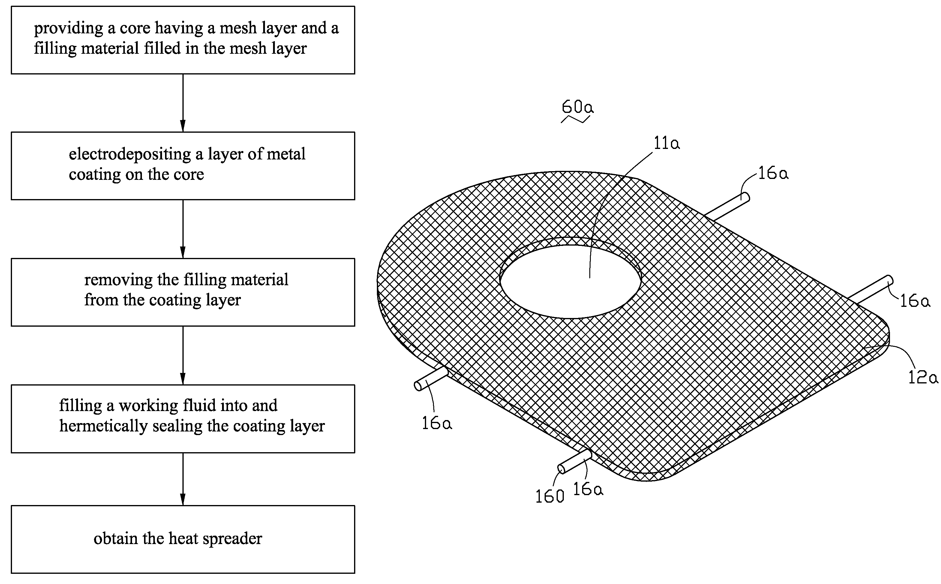
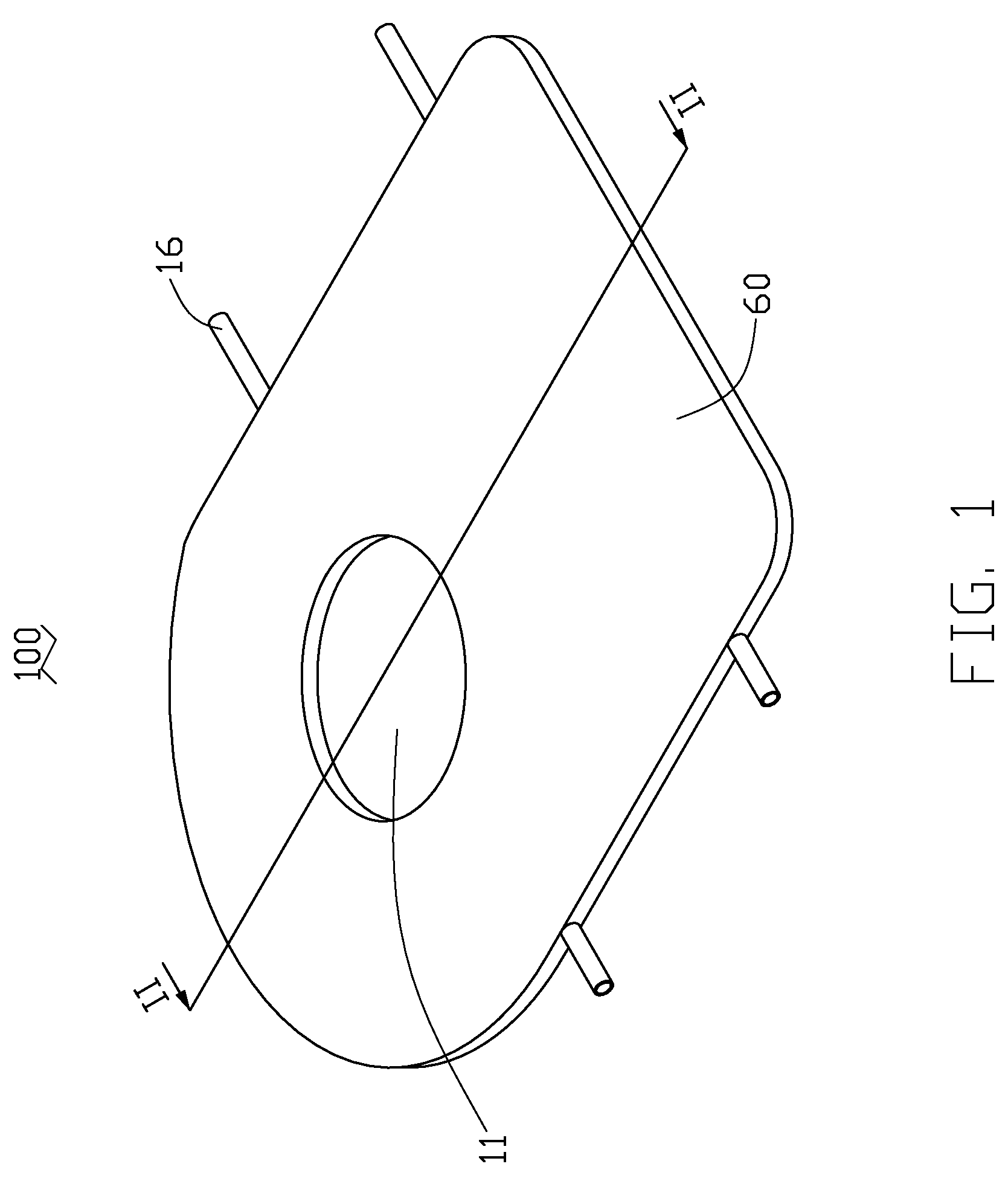
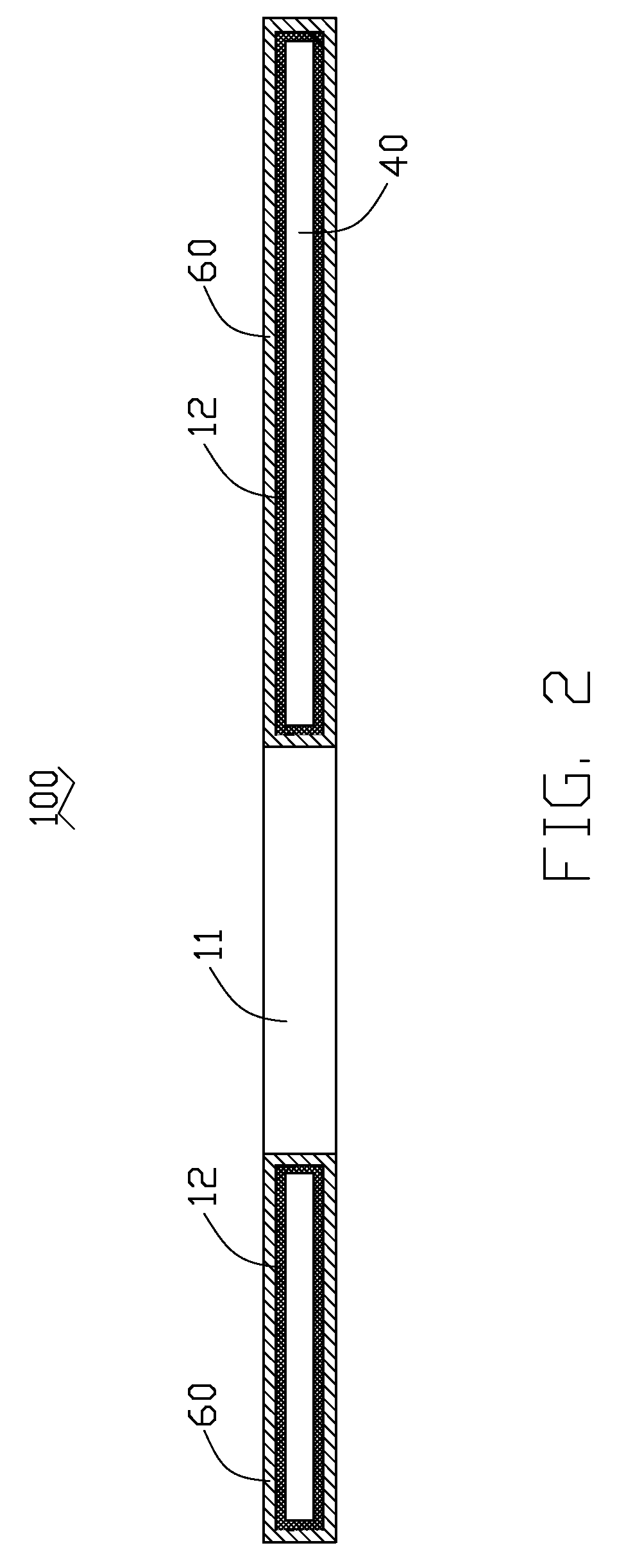
[0017]FIGS. 1 and 2 illustrate a heat spreader 100 formed in accordance with a method of the present invention. The heat spreader 100 is integrally formed and has a flat type configuration. The heat spreader 100 includes a metal casing 60 with a chamber 40 defined therein. A round hole 11 is defined in a middle portion of the metal casing 60 for location of a heat dissipating fan such as a centrifugal blower (not shown). A wick structure 12 is arranged in the chamber 40, lining an inner surface of the metal casing 60 and occupying a portion of the chamber 40. The other portion of the chamber 40, which is not occupied by the wick structure 12 functions as a vapor-gathering region. The metal casing 60 is made of high thermally conductive material such as copper or aluminum. The heat spreader 100 has four open ends 16 extending from two opposite sides thereof, respectively. A working fluid (not shown) is injected into the chamber 40 through the ends 16 and then the heat spreader 100 is...


PUM

PropertyMeasurementUnit
heat removal capacityaaaaaaaaaa
heat fluxaaaaaaaaaa
resistanceaaaaaaaaaa

Abstract

A heat spreader (100) includes a metal casing (60) formed by electrodeposition and defining a vapor chamber (40) therein, and a mesh (12b) lining an inner surface of the metal casing. A method for manufacturing the heat spreader includes: providing a core (60a) having a mesh layer (12a) including a plurality of pores and a filling material (14) filled in the pores of the mesh layer and a major space enclosed by the mesh layer; electrodepositing a layer of metal coating (60b) on an outer surface of the core; removing the filling material from the coating layer and the pores of the mesh layer; and filling a working fluid into the coating layer and hermetically sealing the coating layer to thereby obtain the heat spreader with therein a wick structure (12) formed by the mesh layer and the vapor chamber formed by said major space.

Description

BACKGROUND OF THE INVENTION[0001]1. Field of the Invention[0002]The present invention relates to an apparatus for transfer or dissipation of heat from heat-generating components, and more particularly to a heat spreader having a vapor chamber of a complicated configuration and a method of manufacturing the heat spreader.[0003]2. Description of Related Art[0004]It is well known that heat is generated during operations of a variety of electronic components, such as integrated circuit chips. To ensure normal and safe operations, cooling devices such as heat sinks and / or electric fans are often employed to dissipate the generated heat away from these electronic components.[0005]As progress continues to be made in the electronics art, more components on the same real estate generate more heat. The heat sinks used to cool these chips are accordingly made larger in order to possess a higher heat removal capacity, which causes the heat sinks to have a much larger footprint than the chips. G...

Claims


Application Information

Patent Timeline
Patent Type & Authority Patents(United States)
IPC IPC(8): B23P6/00F28D15/00
CPCF28D15/0283F28D15/046Y10T29/49353
Inventor MENG, JIN-GONGHWANG, CHING-BAI
Owner HON HAI PRECISION IND CO LTD
Why Eureka
Try Eureka