Measuring system with a flow conditioner arranged at an inlet of a measuring tube

a flow conditioner and measuring system technology, applied in the field of measuring systems, can solve the problems of corresponding decline in measurement accuracy, processing, and practically impossible to carry out, and the actual installation conditions of the measuring system are to be considered

Active Publication Date: 2009-10-20
ENDRESS HAUSER FLOWTEC AG
View PDF39 Cites 12 Cited by
  • Summary
  • Abstract
  • Description
  • Claims
  • Application Information

AI Technical Summary

Benefits of technology

[0018]An object of the invention, therefore, is to provide a measuring system for a flowing medium, which, in the context of shortest possible installed length, enables an increase of the Reynolds number of the flow from the process line to the measuring tube, and which, notwithstanding, has a measuring accuracy which is largely insensitive to possible disturbances in the flowing medium upstream of the measuring system, whether in the supply segment and / or in the immediate transition zone between the process line and the actual measuring system.

Problems solved by technology

However, it has been found that, despite the use of flow conditioners of the type named above, already minor disturbances of the flow in the inlet region of the measuring system, especially also in the supply segment of the connected process line located upstream of the measuring system, or in the region of the connection flange on the inlet side, which, if needed, serves to connect the supply segment and the measuring system, are associated with a significant variation of the flow conditions inside the measuring tube lumen, and, thus, with a corresponding decline in the accuracy of measurement.
This processing, however, is practically impossible to carry out, at any rate not without further demands on the user of the measuring system.
In this respect, the actual installation conditions for the measuring system are to be considered not only unforeseeable, but also, as a practical matter, both not adaptable, and, as a result, also not controllable.
However, this can mean a considerable increase in the installed length of the total measuring system.
Given the disadvantages of conventional flow conditioners, it is no wonder that the range of application of measuring systems of the type in discussion is still seen as rather limited.

Method used


Image

  • Measuring system with a flow conditioner arranged at an inlet of a measuring tube
  • Measuring system with a flow conditioner arranged at an inlet of a measuring tube
  • Measuring system with a flow conditioner arranged at an inlet of a measuring tube

Examples


Embodiment Construction

[0124]While the invention is susceptible to various modifications and alternative forms, exemplary embodiments thereof have been shown by way of example in the drawings and will herein be described in detail. It should be understood, however, that there is no intent to limit the invention to the particular forms disclosed, but on the contrary, the intention is to cover all modifications, equivalents, and alternatives falling within the spirit and scope of the invention as defined by the intended claims.

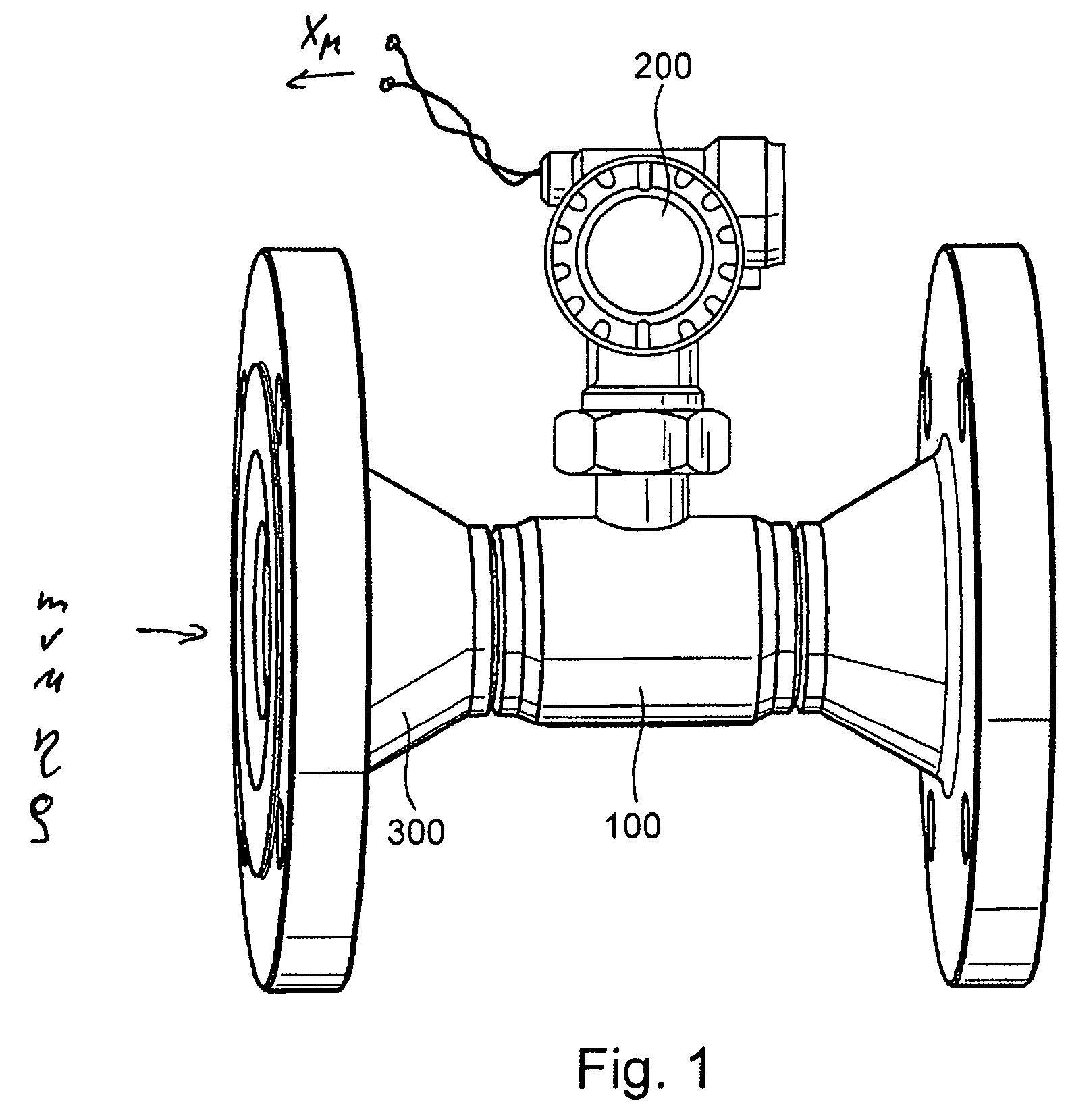
[0125]FIG. 1 shows schematically a measuring system, which may be, to the extent required, modularly assembled. The measuring system is suited for measuring, very robustly, at least one measured variable, especially a mass flow m and / or a volume flow v and / or a flow velocity u and / or some other flow parameter of a medium, for example a liquid, a gas, a vapor, or the like, flowing in a process line (not shown) and for mapping such variable into at least one corresponding, measured valu...


PUM


Abstract

The measuring system is inserted into the course of a process line and serves for registering at least one measured variable of a medium flowing in the process line. The measuring system includes for such purpose a measuring transducer having a measuring tube serving for conveying medium being measured and a sensor arrangement, which has at least one sensor element reacting primarily to the measured variable to be registered, and which delivers by means of at least one sensor element at least one measurement signal influenced by the measured variable. Further, the measuring system includes a measuring electronics communicating with the measuring transducer and using the at least one measurement signal for producing, at least at times, at least one measured value instantaneously representing the measured variable. The measuring tube has, in the case of the measuring system of the invention, a smaller flow cross section than a supply segment of the process line connected to the inlet end of the measuring system. To this end, the measuring system further includes a flow conditioner arranged at the inlet end of the measuring tube and mediating between the measuring tube and the supply segment of the process line. The flow conditioner has a lumen tapering in the direction of the measuring tube. During operation, medium flows through the lumen of the flow conditioner. The flow conditioner includes at least one inner edge arranged upstream of its outlet end and protruding into the lumen of the flow conditioner. During operation, medium conveyed in the flow conditioner flows against the inner edge.

Description

CROSS-REFERENCES[0001]This application is a nonprovisional of U.S. Provisional Application 60 / 832,592 filed on Jul. 24, 2006 and U.S. Provisional Application 60 / 849,769 filed on Oct. 6, 2006 and which claims the benefit of German application numbers 102006034296.8 filed on Jul. 21, 2006 and 102006047815.0 filed on Oct. 06, 2006. It also contains subject matter which is related to the subject matter disclosed in U.S. patent application Ser. No. 11 / 826,993 filed on Jul. 19, 2007.FIELD OF THE INVENTION[0002]The invention relates to a measuring system for measuring with a measuring transducer at least one measured variable, especially a mass flow, e.g. mass flow rate, density, viscosity, pressure, or the like, of a medium flowing in a process line, as well as to a flow conditioner mediating between the measuring transducer and the process line.BACKGROUND OF THE INVENTION[0003]In the field of industrial process measurements technology, especially also in connection with the automation of...

Claims


Application Information

Patent Timeline
Patent Type & Authority Patents(United States)
IPC IPC(8): G01F1/32
CPCG01F1/3209G01F1/86G01F15/185G01F15/00G01F1/88
Inventor HOECKER, RAINER
Owner ENDRESS HAUSER FLOWTEC AG
Why Eureka
Try Eureka