Heat storage system and method for the charging and discharging thereof

a heat storage system and heat storage technology, applied in the field of thermal storage, can solve the problems of not solving the dilemma, the system does not offer any thermal conductivity improvement for phase change materials, any transfer speed improvement on work fluids, etc., and achieves the effect of increasing the number of reynolds and the thermal transfer coefficien

Inactive Publication Date: 2015-08-27
ABENGOA SOLAR NEW TECH SA
View PDF4 Cites 5 Cited by
  • Summary
  • Abstract
  • Description
  • Claims
  • Application Information

AI Technical Summary

Benefits of technology

[0039]Thanks to the aforementioned storage system and the charging method thereof via the lower part, the natural recirculation of the heat-transfer fluid is possible because of the density difference between the heat-transfer fluid in evaporation / condensation in the thermal exchange vertical tubes and the heat-transfer fluid in liquid form in the downpipes. As mentioned above, this natural recirculation means the pass-through increases in the recirculation circuit and therefore the thermal transfer increases (increased Reynolds numbers and thermal transfer coefficient).

Problems solved by technology

If the system were to be charged from the lower part with the solutions that are currently available in the prior art, excess pressure would be generated in the exchange phase which could damage the chamber, as the lower part does not have any room for expansion.
The system does not offer any thermal conductivity improvements for the phase change material or any transfer speed improvements on the work fluid side.
Patent CN201093907Y offers a heat exchanger system between a phase change material and a heat-transfer fluid, characterised in that it is made up of a series of finned tubes arranged in parallel and a system that allows this fluid to circulate in the desired direction, whether charging or discharging the system; however, with this system, as the load is in a vertical ascending direction, the same problem would occur in relation to the expansion of the phase change material mentioned above and therefore this patent would not solve this dilemma.
Both the discharging and charging of the system with a single passage (the fluid only passes through the exchange tubes once) are significantly less effective than discharging and charging via natural recirculation and which takes place from the lower part of the system (a process in which there is an internal recirculation of the heat-transfer fluid with the aim of increasing the flow that goes through the exchange tubes).

Method used


Image

  • Heat storage system and method for the charging and discharging thereof
  • Heat storage system and method for the charging and discharging thereof
  • Heat storage system and method for the charging and discharging thereof

Examples


Embodiment Construction

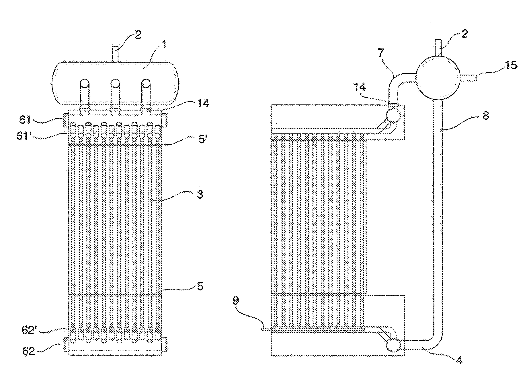
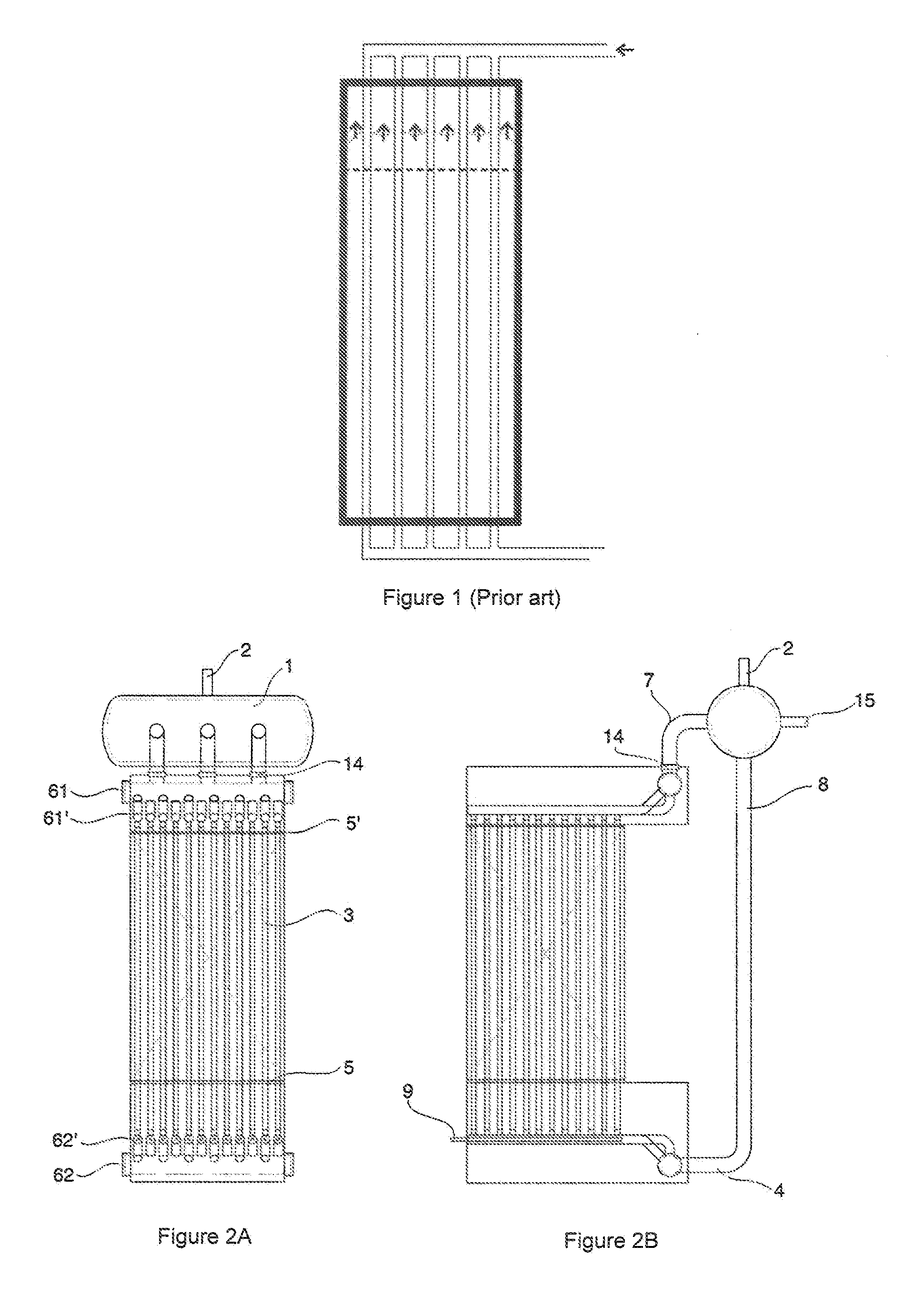
[0072]In order to provide a better understanding of the invention, below is a description, with the help of diagrams, of the preferred embodiment of this invention.

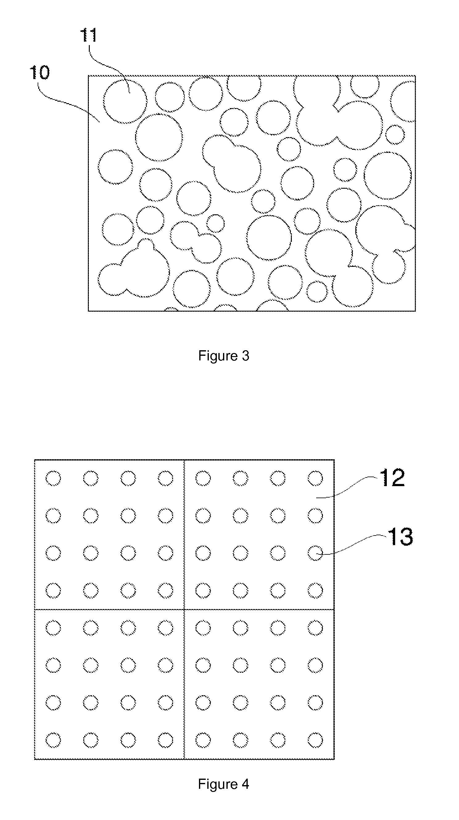
[0073]The thermal storage system of this invention comprises a composite storage material made up of a matrix (12) made of a rigid, graphite, carbon or metal foam (10) with high porosity and thermal conductivity, with said matrix being infiltrated with highly thermally energetic salts based on hydroxides (11) (see FIGS. 3 and 4). This storage material is located inside a casing or container tank.

[0074]As shown in FIG. 2, the storage system also has a heat exchanger made up of heat exchanger tubes (3), preferably vertical, through which the heat-transfer fluid circulates and which pass through the storage material through tube pass-through orifices (13, FIG. 4) so there is direct contact between this storage material and the vertical tubes (3).

[0075]The salt (11) infiltrated in the matrix (12) of the storage material melts...


PUM


Abstract

Thermal storage system and its charging and discharging process using a heat-transfer fluid. The system includes a phase change storage material contained in a casing that is penetrated by heat exchanger tubes (3), preferably vertical ones, connected at their lower end with at least one lower chamber (62) via lower sub-chambers (62′) which include a series of injectors (9) for enabling the heat-transfer fluid to be inserted in gas form; at the upper end, these tubes (3) connect via upper sub-chambers (61′) with at least one upper chamber (61) which in turn is connected to a boiler (1) from which downpipes (8) extend via which heat-transfer fluid in liquid form circulates, located outside of the casing, connecting the aforementioned boiler (1) to the lower chamber (62), which enables the natural circulation of the heat-transfer fluid within the system.

Description

TECHNICAL FIELD OF THE INVENTION[0001]This invention relates to the field of thermal storage using phase change material (PCM). In particular, it refers to a thermal energy storage system suitable for being charged and discharged with a heat-transfer fluid in a thermal exchange process (evaporation / condensation) and which stores heat in the form of latent heat of fusion of a phase change material.[0002]The thermal storage system proposed can be used in solar thermal plants for steam generation and in production processes in which the storage of heat may be an interesting differentiating factor from an economic point of view.BACKGROUND OF THE INVENTION[0003]Phase change materials can be an interesting, efficient and high energy density alternative for storing heat and particularly for applications at constant temperature. There are countless phase change materials and exchange system related thereto, which are aimed at, among others:[0004]Improving the thermal conductivity of the pha...

Claims


Application Information

Patent Timeline
Patent Type & Authority Applications(United States)
IPC IPC(8): F28D20/00
CPCF28D20/0034F01K3/00F22B1/028F22B1/10F22B33/18F28D7/16F28D20/021F28D2021/0061F28F9/0275Y02E60/14
Inventor JOVE LLOVERA, ALEIXPRIETO RIOS, CRISTINA
Owner ABENGOA SOLAR NEW TECH SA
Why Eureka
Try Eureka