Heating furnace for heating annular component

A ring-shaped component and a heating furnace technology, which is applied in the field of heat treatment, can solve the problems of not being able to fully utilize the heat insulation and sealing the cavity, the large difference in heating efficiency, and the large radial scale of the device body.

Active Publication Date: 2017-01-04
BEIJING GOLDWIND SCI & CREATION WINDPOWER EQUIP
View PDF4 Cites 3 Cited by
  • Summary
  • Abstract
  • Description
  • Claims
  • Application Information

AI Technical Summary

Problems solved by technology

[0005] However, in the actual application process, it was found that the heating efficiency of the heating furnace equipped with the above-mentioned cylindrical adiabatic closed cavity is relatively different when heating different types of bearings, and the heating efficiency of bearings with larger diameters is generally higher, while The heating efficiency of bearings with relatively small diameter and thick wall is relatively low, and it cannot play the role of insulating and sealing the cavity
[0006] In addition, facing the large-diameter annular component, an adiabatic cavity is set in the central area, which occupies a large radial space of the heating furnace body, which will cause the overall radial dimension of the device body to be too large, or even exceed the allowable width of transportation, which is not suitable for transportation and mobile factories. bring great difficulty

Method used


Image

  • Heating furnace for heating annular component
  • Heating furnace for heating annular component
  • Heating furnace for heating annular component

Examples


Embodiment Construction

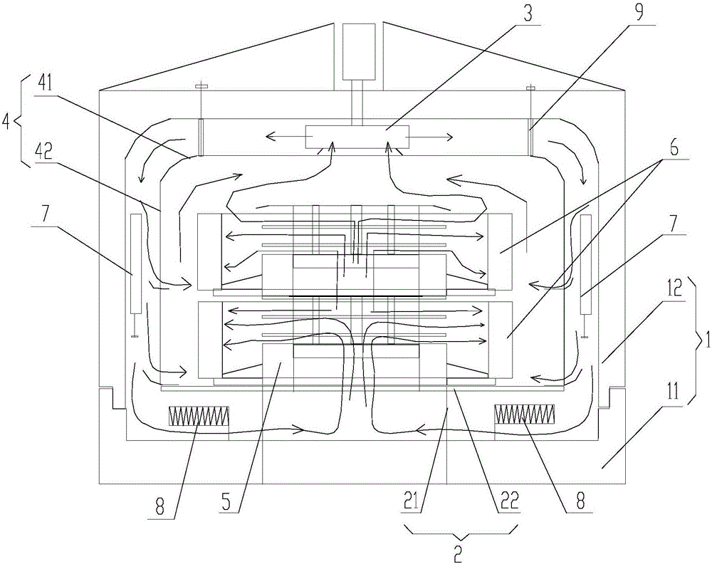
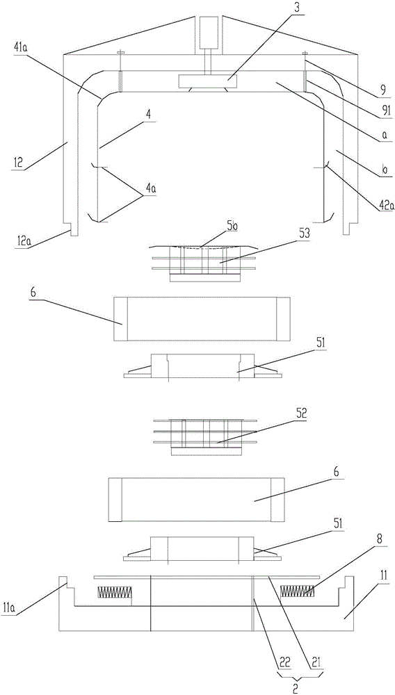
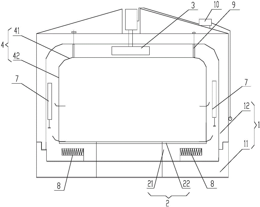
[0045] Aiming at the technical problem of different heating furnace efficiency for different types of bearings in the prior art, the present invention has carried out a large number of experiments and theoretical studies, and found that the main problem leading to the different heating efficiency of the bearings in the prior art is: cylindrical adiabatic closed cavity It is only suitable for annular components whose inner diameter is much larger than the wall thickness. Only in this way can it meet the demand for enhanced heat transfer with narrow flow passages for annular thin-wall heating structures. When the inner diameter of the annular component is small (especially when the inner diameter of the annular component is as small as 200mm and the radial thickness is as small as 10mm or less), the significance of the existence of the cylindrical heat-insulating closed cavity is greatly reduced.

[0046] On the basis of the above research findings, the present invention further ...


PUM


Abstract

The invention discloses a heating furnace for heating an annular component. The heating furnace comprises a furnace body, a heating medium driving component, a supporting piece, a flow guiding component and a hollow cylindrical body. A part of heat media in the heating furnace is sprayed on the outer peripheral surface of the annular component through the flow guiding component, and the other part of the heat media flows through an inner cavity of the hollow cylindrical body and is blown to the inner peripheral surfaces of bearings through a second heat medium channel on the hollow cylindrical body so that the inner peripheral surfaces of the bearings can be heated. Thus, the hollow cylindrical body has an effect of dividing a gas flow to a certain extent, and the upper end surface of the hollow cylindrical body is of a sealed structure, so that the flowing gas flow is completely converted into an effective heat exchange gas flow and limited in heat exchange spaces on the surfaces of the bearings. The high reynolds number of the gas flow in heat exchange areas of the bearings as well as the high heat exchange speed of the surfaces of the bearings and the gas flow are obtained, the flow speed is multiplied at the same volume flow rate, and the flowing gas flow is completely converted into the effective heat exchange gas flow; and at the same flow speed, the volume flow rate is decreased substantially, the temperature raising speed of the gas flow is multiplied, thus, the heating efficacy is improved, and the power of a electric heater is decreased greatly.

Description

technical field [0001] The invention relates to the technical field of heat treatment, in particular to a heating furnace for heating ring components. Background technique [0002] At present, ring parts such as large-scale bearings of wind power generators are generally assembled on components such as motor shafts through a shrink-fit installation method. The so-called thermal sleeve installation method refers to putting the bearing in hot liquid or hot gas for heating before installation, using the principle of thermal expansion and contraction to make the inner diameter of the bearing expand and increase, and the expanded bearing is installed on the motor shaft, and the temperature is lowered. The rear bearing is then fixed on the motor shaft. Wherein, the bearing is generally heated in a heating furnace, and air is usually used as a heat medium in the heating furnace. The specific structure of a heating furnace device in the prior art is given below. [0003] The heati...

Claims


Application Information

Patent Timeline
IPC IPC(8): C21D9/40
CPCC21D9/40C21D1/767C21D9/663C21D9/673F27B11/00F27D7/04F27D2007/045F27B1/10F27D5/00F27D2005/0081B23P11/025
Inventor 马盛骏
Owner BEIJING GOLDWIND SCI & CREATION WINDPOWER EQUIP
Why Eureka
Try Eureka