Electric motor with reduction gear mechanism

a technology of gear mechanism and electric motor, which is applied in the direction of magnetic circuit rotating parts, portable power-driven tools, magnetic circuit shape/form/construction, etc., can solve the problem of diffuse reflection noise proportion, reduce the number of parts and assembling steps of reduce the noise emitted from the electric motor with the reduction gear mechanism.

Active Publication Date: 2009-10-20
MITSUBA CORP
View PDF12 Cites 11 Cited by
  • Summary
  • Abstract
  • Description
  • Claims
  • Application Information

AI Technical Summary

Benefits of technology

[0007]An object of the present invention is to reduce noises emitted from the motor body to the outside.
[0025]According to the present invention, since the noise-preventing means is disposed outside the motor yoke, noises emitted from the interior of the motor yoke through the opening portion can be collectively removed before propagating to other wirings. Therefore, the noises emitted from the electric motor with reduction gear mechanism can be reduced.
[0026]Also, according to the present invention, since the brushes are grounded on the motor yoke and noises that have not been removed by the noise-preventing means are returned back to the interior of the motor body via the gear-case-side grounding terminal and the motor-yoke-side grounding terminal, emission of noises to the outside of the motor can be reduced.
[0027]Further, according to the present invention, since the grounding terminal is formed by bending a portion of the connecting plate on the negative-pole side and the grounding terminal is caused to contact with the ground protrusion portion provided on the gear case in an elastically deformed state thereof, sufficiently flexing length of the gear-case-side grounding terminal can be assured even in a narrow space, whereby the power-feeding circuit of the electric motor with reduction gear mechanism can be grounded on the gear case reliably. Also, since the gear-case-side grounding terminal can be reliably grounded on the gear case without using a fastening member such as a screw, the number of parts and the number of assembling steps for the electric motor with reduction gear mechanism can be reduced.
[0028]Further, according to the present invention, the partition wall projecting between the pair of brush-side connecting plates is provided in the accommodating case. Therefore, when each of the pair of brush-side connecting plates is soldered to a corresponding connection portion of the brush holder, even if solder flows from one of the brush-side connecting plates, the flow of the solder is stopped by the partition wall. That is, the flowing solder can be prevented from expanding to the brush-side connecting plate. Thereby, it is possible to prevent short-circuiting caused due to the flow of the solder.

Problems solved by technology

Therefore, in the motor in which the noise-preventing element such as a choke coil or a capacitor is provided on the brush holder, there is such a drawback that a portion of the diffusely reflected noises flies to a wiring located on a side of the power-feeding terminal rather than the choke coil or capacitor and is emitted, without being absorbed by the noise-preventing element, from the motor yoke to the outside via a wiring of a connector provided on the gear case.

Method used


Image

  • Electric motor with reduction gear mechanism
  • Electric motor with reduction gear mechanism
  • Electric motor with reduction gear mechanism

Examples


Embodiment Construction

[0047]An embodiment of the present invention will be explained below in detail with reference to the drawings.

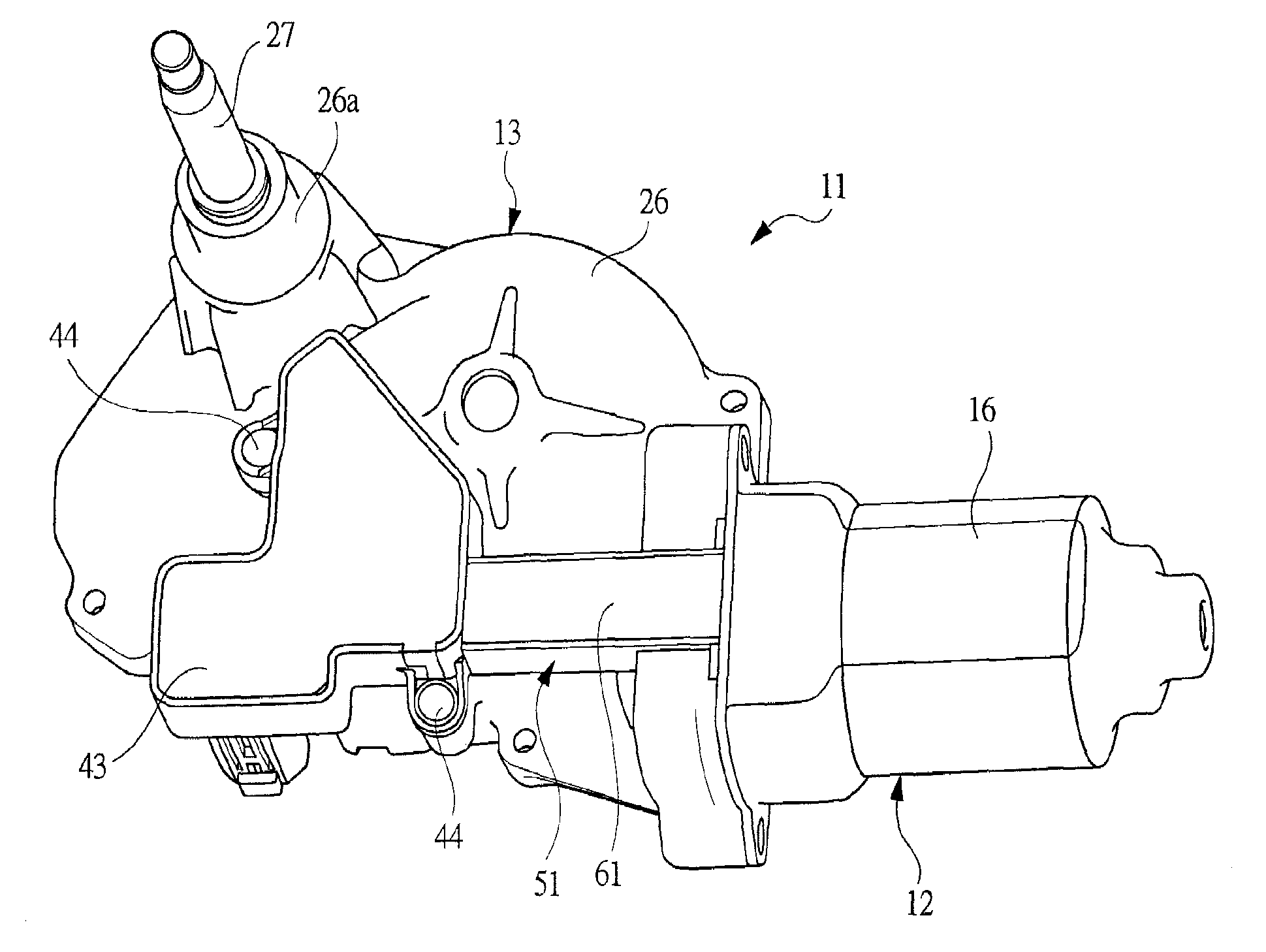
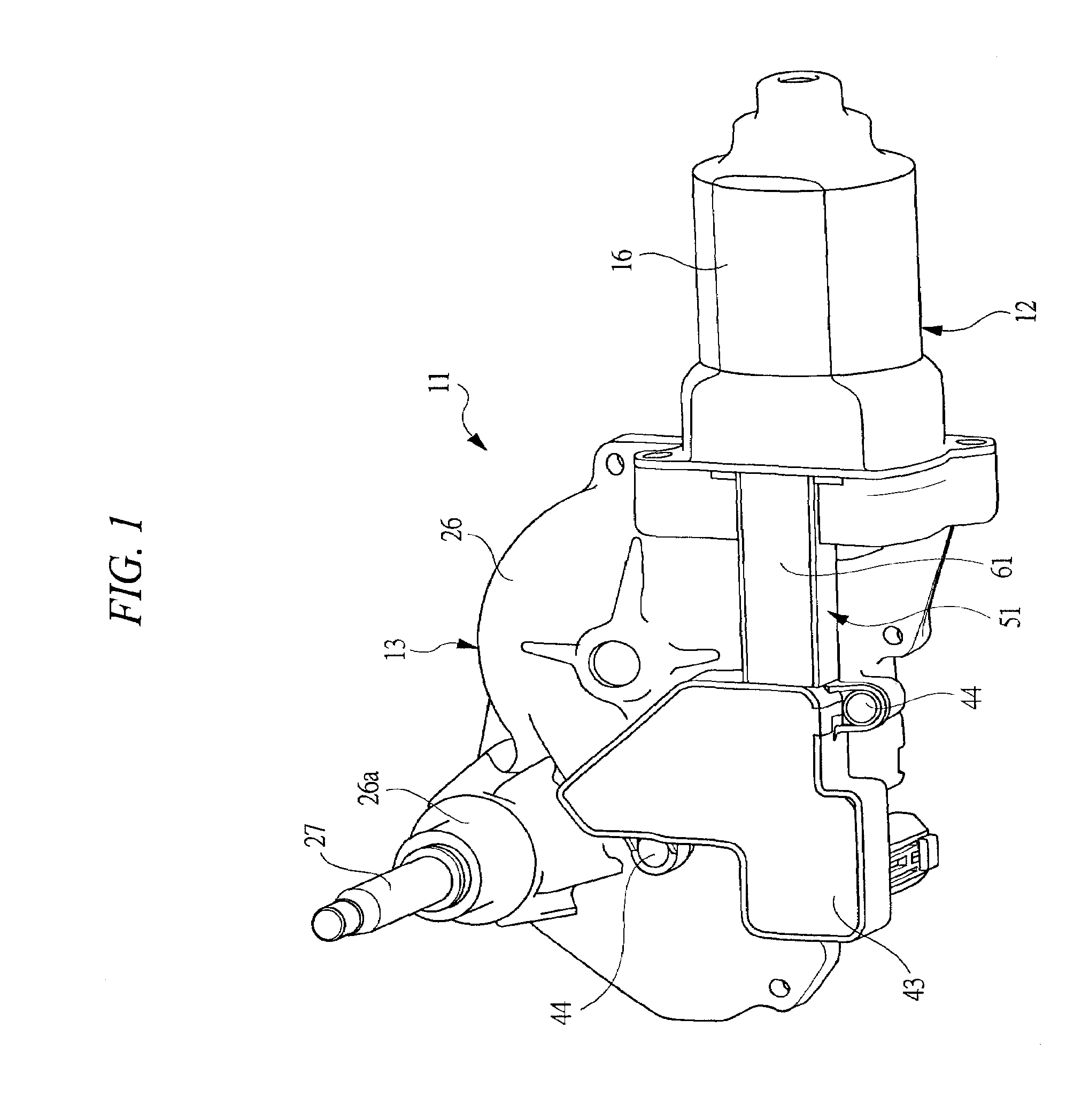
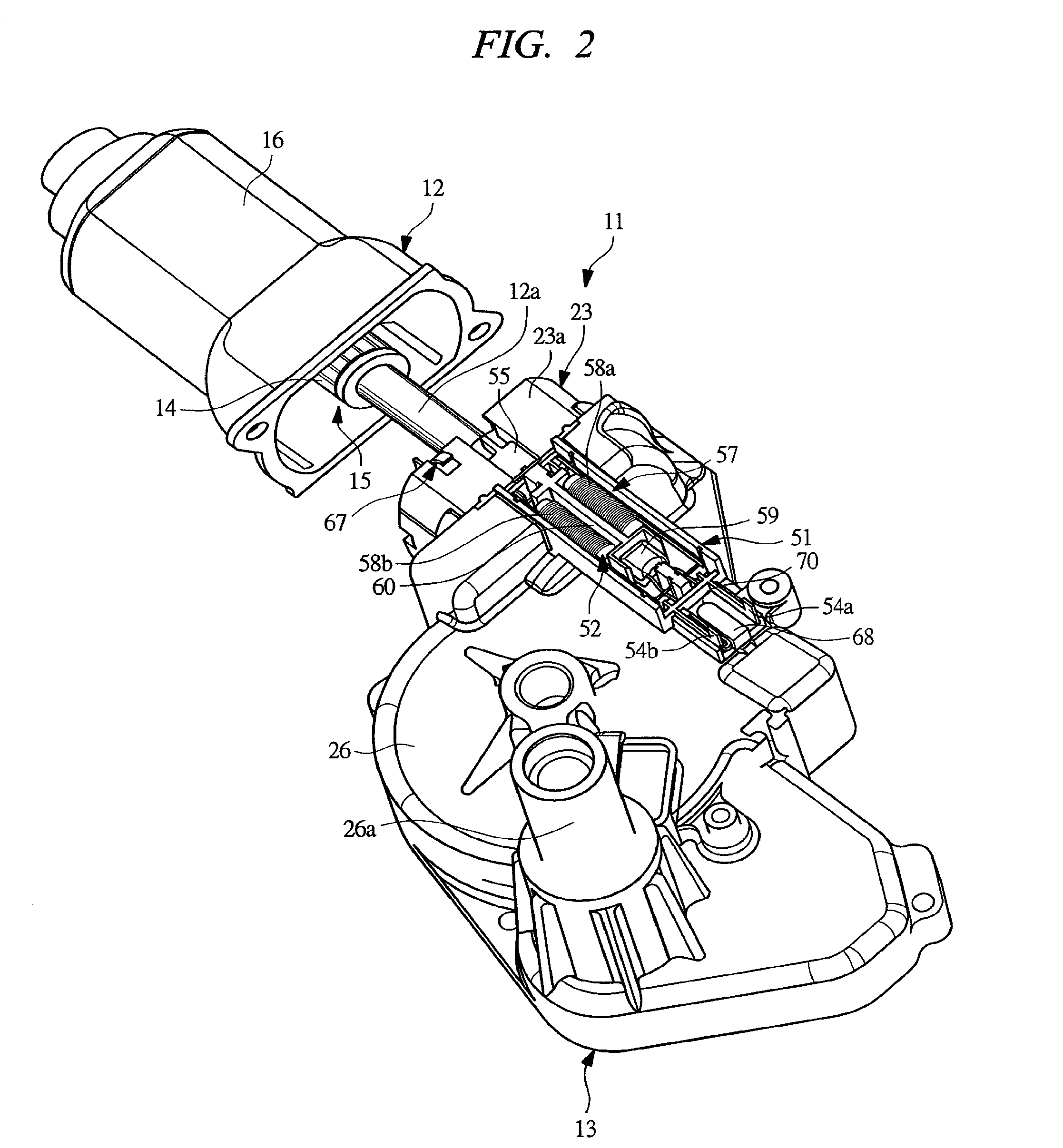
[0048]FIG. 1 is a perspective view showing a wiper motor according to an embodiment of the present invention and FIG. 2 is an exploded perspective view of the wiper motor shown in FIG. 1.

[0049]A wiper motor 11 shown in FIG. 1 is used as a drive source for a rear wiper apparatus provided on a vehicle, and serves as an electric motor with reduction gear mechanism in which a motor body 12 and a reduction gear apparatus 13 are constituted as a single unit.

[0050]As shown in FIG. 2, the motor body 12 serves as a motor with brush provided with a rotating shaft 12a, wherein a commutator 14 and an armature core not shown are fixed to the rotating shaft 12a. A plurality of coils (armature coils) not shown are wound around slots of the armature core, and ends of the coils are respectively connected to corresponding segments of the commutator, whereby an armature 15 is composed of the c...


PUM


Abstract

In a wiper motor including a motor body and a reduction gear apparatus, an accommodating case is integrally provided on a brush holder provided to the motor body, and this accommodating case is disposed on an outer face of a gear case so as to project from a motor yoke. A noise-preventing element including a pair of choke coils and a bidirectional varistor is accommodated in the accommodating case, and the noise-preventing element is connected between a power-feeding terminal of a connector provided on the gear case and brushes. Noises acting on a power-feeding circuit are absorbed by the noise-preventing element and noises which have leaked to the outside via an opening portion of the motor yoke are absorbed by the noise-preventing element.

Description

CROSS-REFERENCE TO RELATED APPLICATIONS[0001]Applicant hereby claims foreign priority benefits under U.S.C. §119 from Japanese Patent Application No. 2006-206459 filed on Jul. 28, 2006, No. 2006-206460 filed on Jul. 28, 2006, No. 2006-206461 filed on Jul. 28, 2006, No. 2007-163459 filed on Jun. 21, 2007, and No. 2007-163460 filed on Jun. 21, 2007, the contents of which are incorporated by reference herein.FIELD OF THE INVENTION[0002]The present invention relates to an electric motor with reduction gear mechanism including a motor body provided with a rotating shaft and a reduction gear mechanism for decelerating rotation of the rotating shaft to output it from an output shaft.BACKGROUND OF THE INVENTION[0003]An electric motor activated by a power source such as a battery loaded in a vehicle is generally used as a drive source for a wiper apparatus, a power window apparatuses, an electric sun-roof apparatus, or the like which is provided in the vehicle. In order to adapt the electric...

Claims


Application Information

Patent Timeline
Patent Type & Authority Patents(United States)
IPC IPC(8): H02K11/00
CPCH02K5/148H02K23/66H02K11/024H02K7/1166H02K5/225B25F5/006H02K11/026H02K11/028
Inventor KANDA, SATOSHIHATORI, SHUICHI
Owner MITSUBA CORP
Why Eureka
Try Eureka