Shrouded turbofan bleed duct

a turbofan and bleed duct technology, which is applied in the direction of hot gas positive displacement engine plants, heat exchange equipment, lighting and heating equipment, etc., can solve the problems of requiring further development, time and cost, and undesirable to leave the bleed valve, and achieve the effect of not degrading the performance of the bleed du

Active Publication Date: 2009-10-27
GENERAL ELECTRIC CO
View PDF7 Cites 78 Cited by
  • Summary
  • Abstract
  • Description
  • Claims
  • Application Information

AI Technical Summary

Benefits of technology

[0018]A bleed duct is configured for bleeding fan air from the fan bypass duct in a turbofan aircraft engine. The bleed duct includes a tubular conduit having an inlet and outlet at opposite ends. The conduit is configured in flow area for recovering pressure from speeding fan air bled therethrough. A shroud extends forwardly from the duct inlet for suppressing dynamic pressure oscillations inside the conduit without degrading the pressure recovery.

Problems solved by technology

This configuration may result in the formation of a Hartmann Generator that causes unstable dynamic pressure oscillations inside the closed bleed duct which can lead to sonic fatigue and subsequent damage of the associated parts.
However, in the continuing development of the commercial application described above, it is undesirable to leave the bleed valve even slightly open when it should be closed for increasing the overall efficiency of the turbofan engine.
This presents a significant design problem since the basic configuration of the turbofan engine has been fixed based on previous development and expense rendering impractical the redesign thereof.
There are many components found in the bleed system for the compressor and fan, including the cooperating heat exchanger therefor, for which a change in inlet design of the bleed duct could have adverse consequences requiring further development, time, and cost.

Method used


Image

  • Shrouded turbofan bleed duct
  • Shrouded turbofan bleed duct
  • Shrouded turbofan bleed duct

Examples


Embodiment Construction

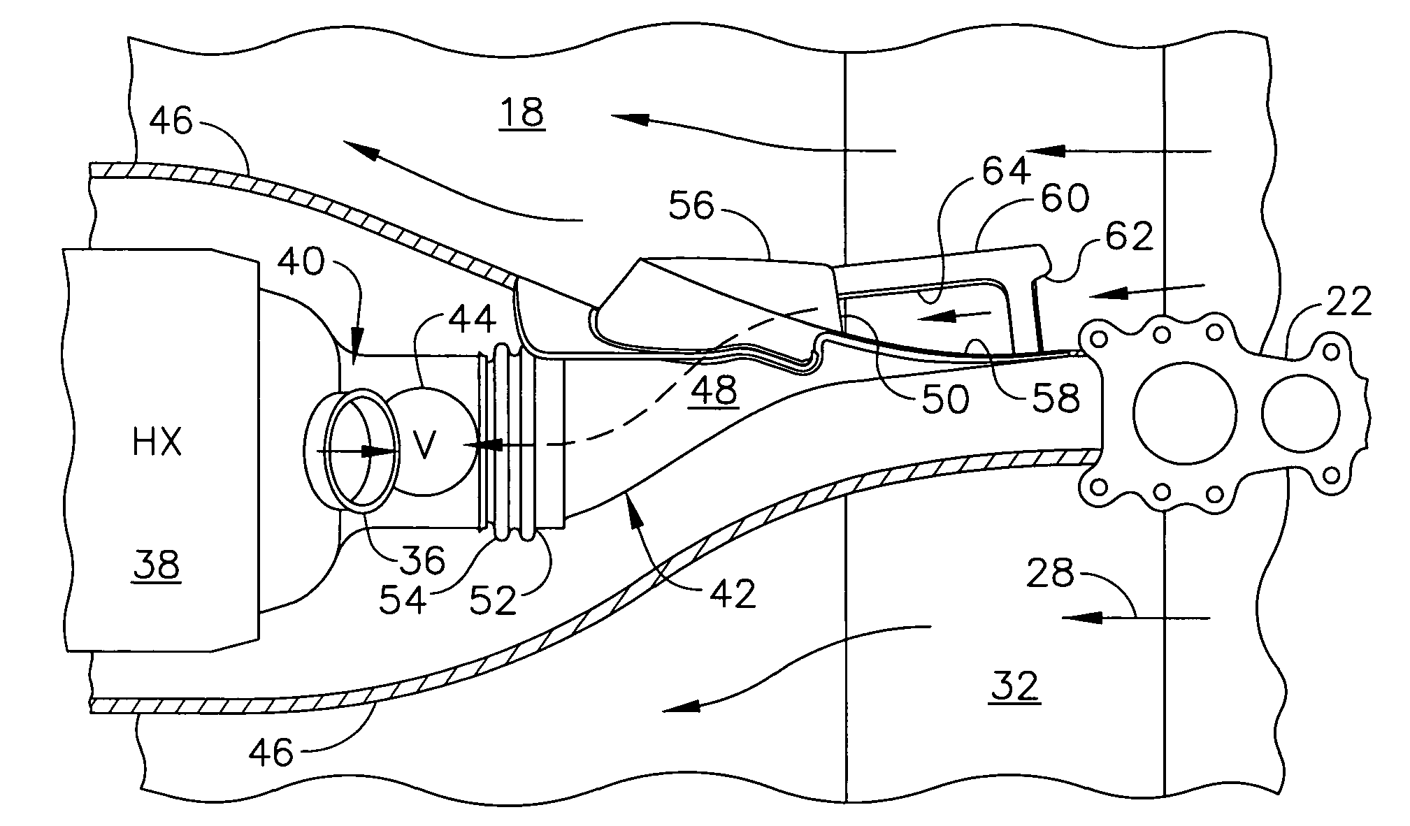
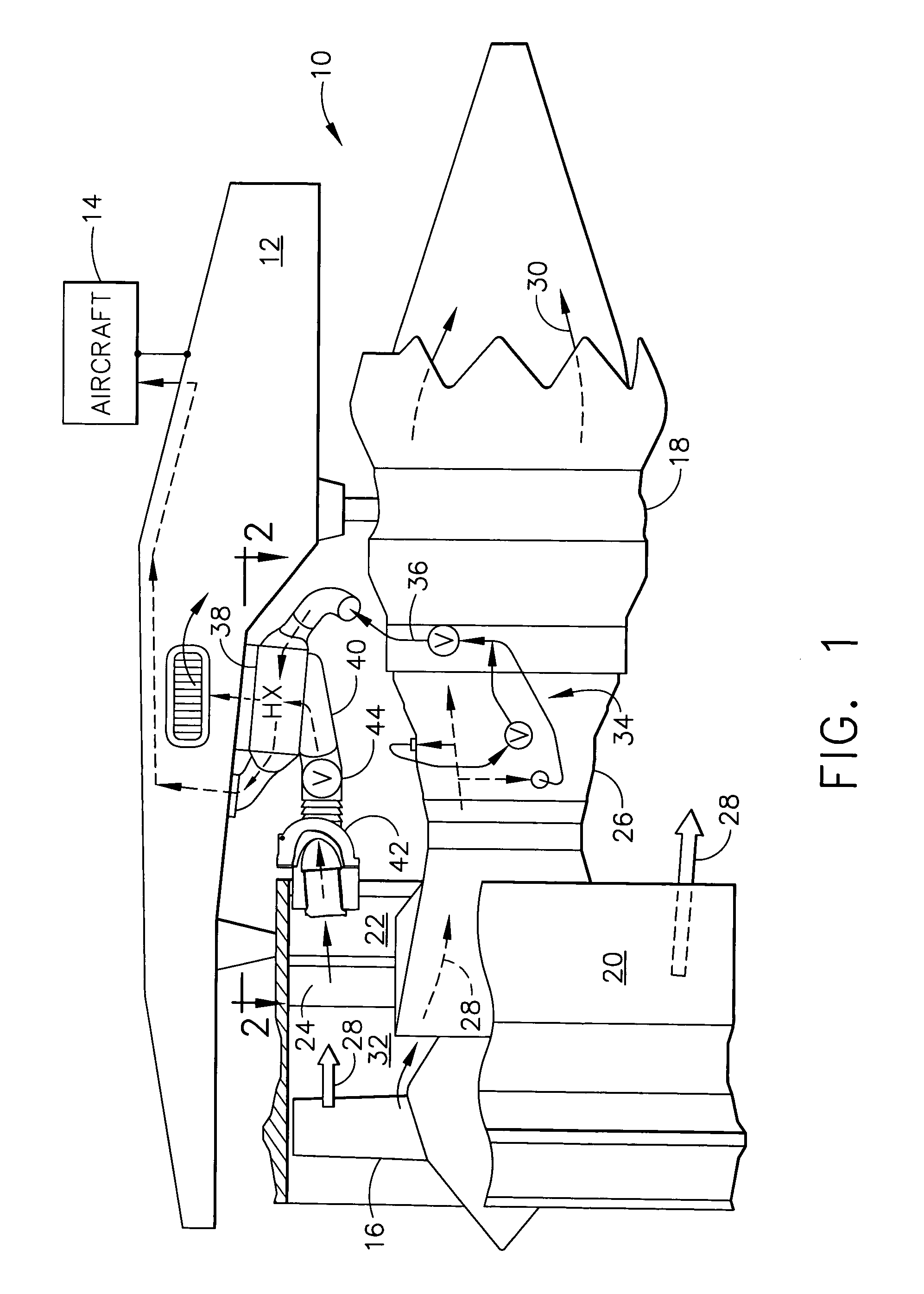
[0033]Illustrated schematically in FIG. 1 is a turbofan gas turbine aircraft engine 10 suitably mounted to the supporting pylon 12 in an aircraft 14, shown schematically. The engine includes a fan 16 powered by a core engine 18 coaxially joined thereto. The fan 16 includes a row of fan blades mounted inside an annular fan casing 20, with the fan casing being mounted to the forward end of the core engine by a row of fan struts 22, and another row of fan outlet guide vanes (OGVs) 24.

[0034]The core engine includes a multistage axial compressor 26 having sequential stages of stator vanes and rotor blades which pressurize in turn the incoming air 28. Pressurized air is discharged from the compressor and mixed with fuel in the combustor of the core engine for generating hot combustion gases 30 that flow downstream through high and low pressure turbines which extract energy therefrom prior to discharging the combustion gases from the outlet of the core engine. The high pressure turbine pow...


PUM


Abstract

A bleed duct is configured for bleeding fan air from the fan bypass duct in a turbofan aircraft engine. The bleed duct includes a tubular conduit having an inlet and outlet at opposite ends. The conduit is configured in flow area for recovering pressure from speeding fan air bled therethrough. A shroud extends forwardly from the duct inlet for suppressing dynamic pressure oscillations inside the conduit without degrading the pressure recovery.

Description

BACKGROUND OF THE INVENTION[0001]The present invention relates generally to gas turbine engines, and, more specifically, to air bleeding therein.[0002]Modern aircraft are typically powered by turbofan aircraft engines. The turbofan engine is a specialized form of gas turbine engine in which air flows through a fan and compressor that pressurizes the air in turn which is then mixed with fuel in a combustor for generating hot combustion gases.[0003]A core engine includes the compressor and combustor and cooperating high and low pressure turbines that extract energy from the combustion gases for powering the compressor and fan, respectively.[0004]Most of the inlet air is pressurized by the fan and bypasses the core engine for producing a majority of propulsion thrust for powering the aircraft in flight. A portion of the fan air is directed into the core engine wherein it is further pressurized in multiple stages of increasing pressure in the compressor therein.[0005]The turbofan engine...

Claims


Application Information

Patent Timeline
Patent Type & Authority Patents(United States)
IPC IPC(8): F02C6/04
CPCF02C6/08F02K3/06F02C7/32F28F27/02F28D2021/0021F28F2250/106
Inventor KRAFT, ROBERT EUGENEGIBBENS, NELSON DIRKHETICO, ROLF ROBERTGROLL, WILLIAM CHARLESBAILEY, WILLIAM ANDREWSTOKER, JAMES EDWARD
Owner GENERAL ELECTRIC CO
Why Eureka
Try Eureka