System and method for diverting liquids from foodstuff during preparation in a frying pan

a technology of cooking liquid and frying pan, which is applied in the direction of milk preservation, baking vessels, instruments, etc., can solve the problem of high restriction of the movement of the frying pan on top of the supporting structure, and achieve the effect of preventing this greas

Active Publication Date: 2009-10-27
STANCZAK EDMUND A
View PDF24 Cites 11 Cited by
  • Summary
  • Abstract
  • Description
  • Claims
  • Application Information

AI Technical Summary

Benefits of technology

[0007]The frying pan supporting structure, which is preferably a ring structure but which could be shaped otherwise, includes a pair of spaced apart arms for retaining the angled frying pan thereby preventing it from sliding off of the top of the supporting structure. The frying pan supporting structure further includes a handle for manipulating the device. The oil or grease in flowing form substantially collects under the shield which prevents splashing and splattering. The shield may be made of a variety of configurations, but generally is a substantially flat sheet of a half-moon configuration and an element to retain the shield on the frying pan, such as a hook. The shield may be fitted with a wall. The user positions the shield at the low end of the angled frying pan. During use the oil and grease escaping from the foodstuff is directed by gravity to the lowest end of the frying pan, which is that area substantially under the shield.
[0008]The system of the disclosed invention provides a broad variety of advantages over prior approaches to dealing with excessive oil and grease resulting from cooking. The approach of the instant invention provides for straight-forward mechanical separation of most of the oil and grease from around the foodstuff while leaving adequate pan surface area for proper cooking. The disclosed invention accomplishes this using a conventional frying pan, which can be of a great variety of sizes, shapes and depths. The supporting structure is configured in general as a ring so as to fit upon virtually any standard cooking surface, including electric coils, flat surfaced radiant glass stovetops, and gas models. Because of the provision of a pair of spaced apart arms fitted to the ring, movement of the frying pan on top of the supporting structure is highly restricted. This can be accomplished without the need of securing the frying pan to the supporting structure, thereby allowing the cook to readily move between horizontal cooking to angled cooking. Accordingly, the foodstuff can initially be seared horizontally then cooking of the foodstuff can be completed at an angle. This is in sharp contrast to known pans having permanent angled bases as well as to known pans having supporting structures that are fixed to the base of the frying pan.
[0009]Because the supporting structure essentially has a hollow center, heat is able to easily and directly radiate from the cooking surface to the bottom of the frying pan and is focused thereby. The supporting structure can also be modified to incorporate ring holes of various sizes, shapes and locations designed to control pan heat distribution. The supporting structure may be made of a variety of materials (preferably stainless steel but also possibly aluminum) which are easily cleaned and durable.
[0012]In addition to covering collected grease and thereby preventing this grease from both splashing when the pan is handled and from splattering during cooking, the shield separates the pan into two distinct areas, one being for cooking and the other being for grease collection. The shield also prevents the foodstuff from moving from its cooking area to the grease collection area during cooking. The shield fits a broad variety of pans having different side heights, side flares and side corner radii.

Problems solved by technology

Because of the provision of a pair of spaced apart arms fitted to the ring, movement of the frying pan on top of the supporting structure is highly restricted.

Method used


Image

  • System and method for diverting liquids from foodstuff during preparation in a frying pan
  • System and method for diverting liquids from foodstuff during preparation in a frying pan
  • System and method for diverting liquids from foodstuff during preparation in a frying pan

Examples


Embodiment Construction

[0023]In the following figures, the same reference numerals will be used to refer to the same components. In the following description, various operating parameters and components are described for one constructed embodiment. These specific parameters and components are included as examples and are not meant to be limiting.

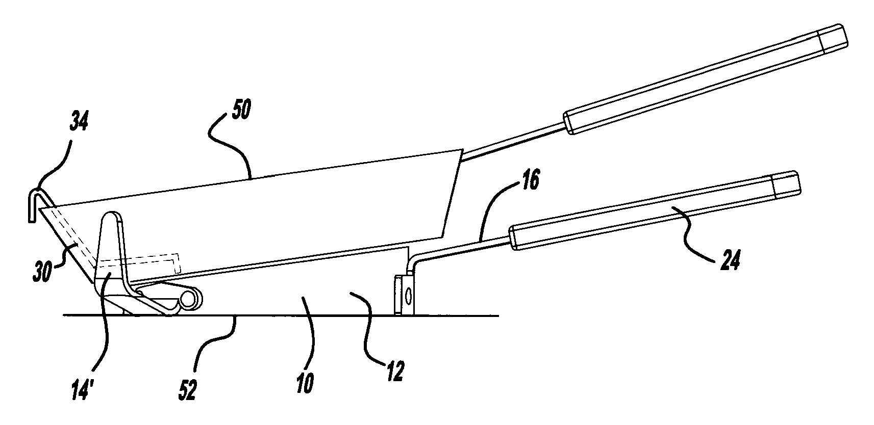
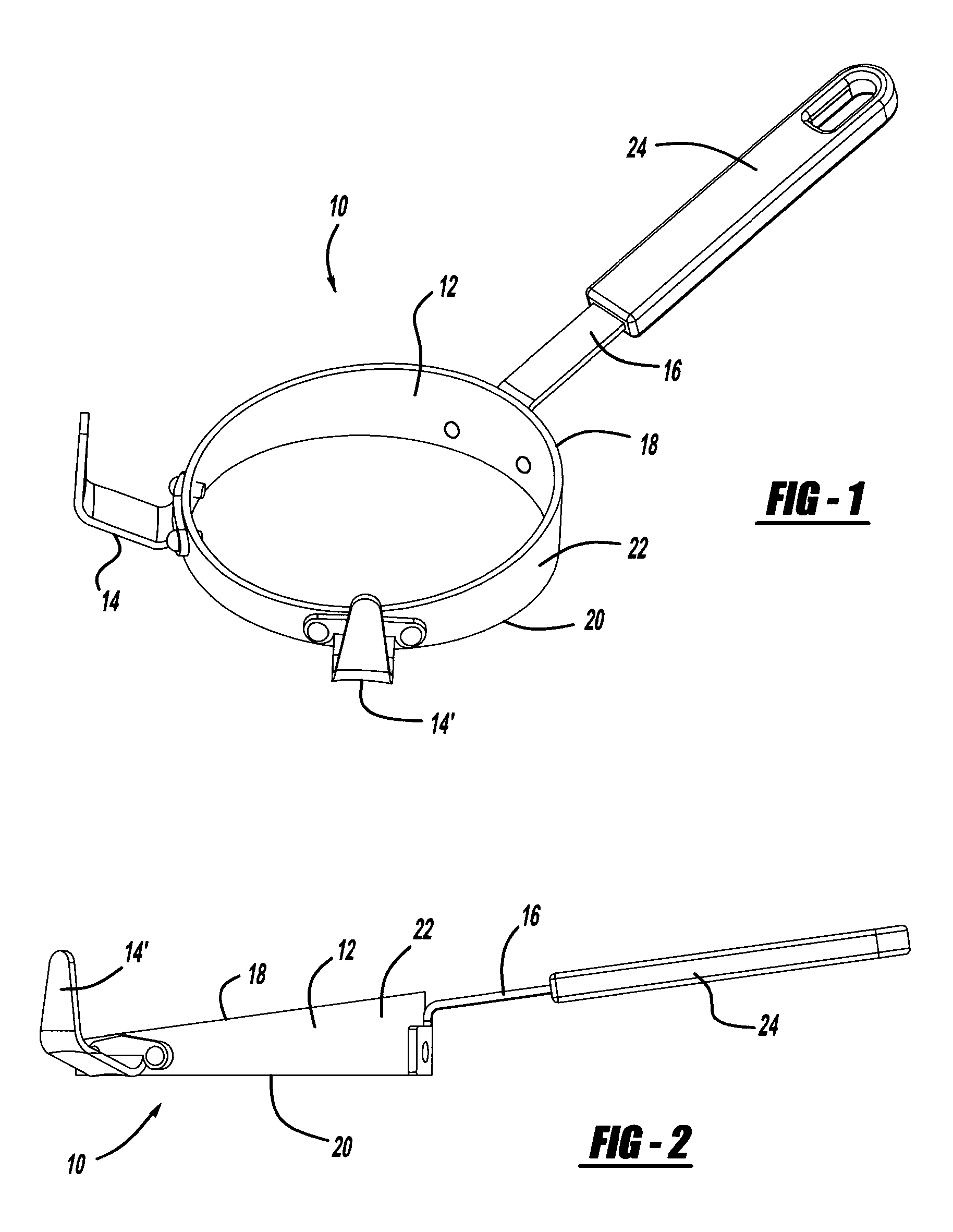
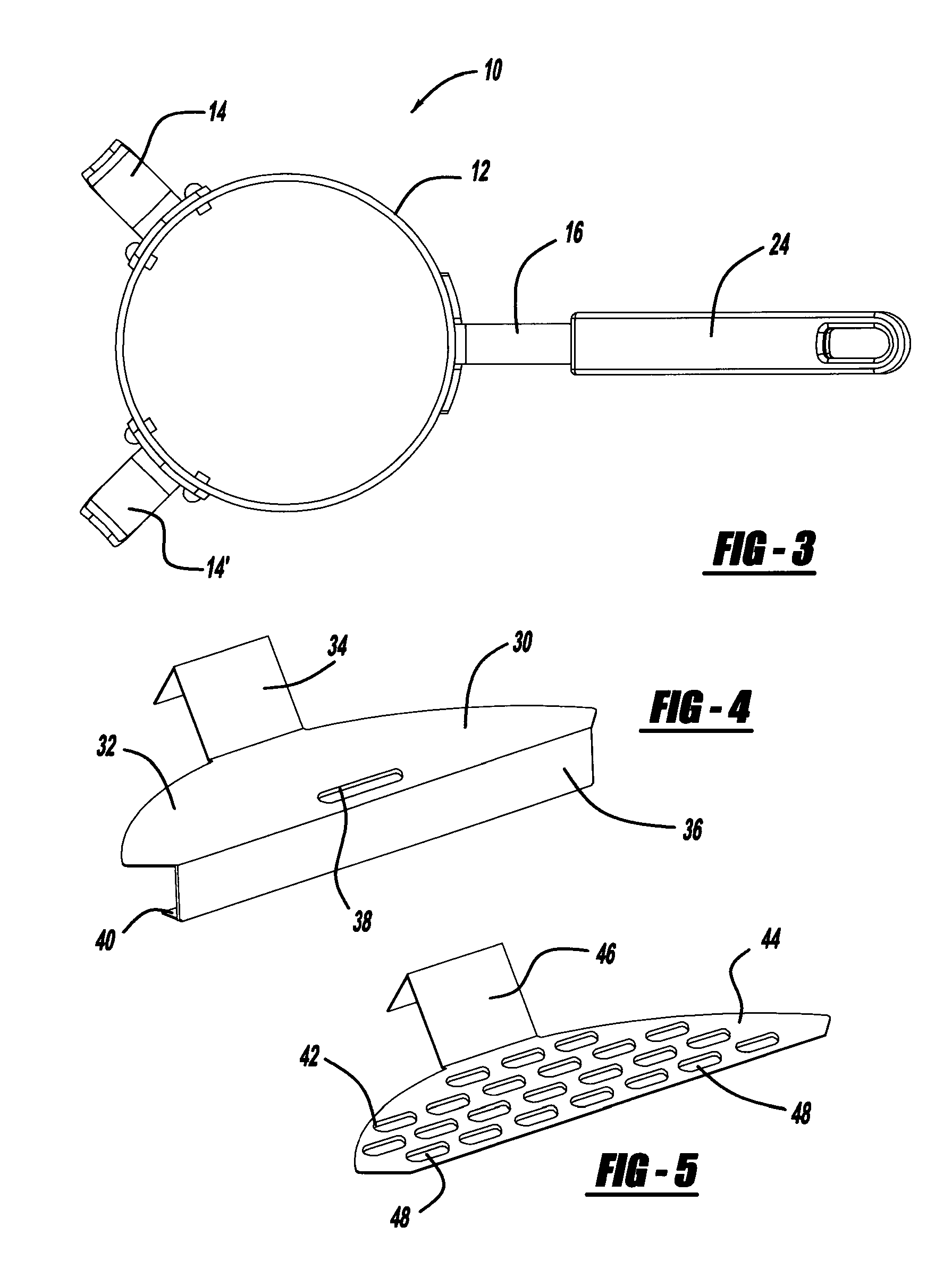
[0024]With reference to FIGS. 1, 2 and 3, a perspective and a side view of a frying pan supporting structure, generally illustrated as 10, a side view of the frying pan supporting structure 10, and a top plan view of the frying pan supporting structure are respectively shown. The frying pan supporting structure 10 includes a body 12, a pair of frying pan supporting arms 14 and 14′, and a handle 16.

[0025]The body 12 is illustrated as having a ring configuration as such a configuration may be the most desirable. However, it is to be understood that other configurations, such as a square, rectangular, triangular, octagonal, or other shape may be used as well. Regardl...


PUM


Abstract

A system for directing cooking liquids away from cooking foodstuff in a frying pan is disclosed. The system includes a frying pan supporting structure and a shield. The frying pan supporting structure includes a bottom side for placement on a heating element and a top side upon which said frying pan rests. The bottom side and the top side are angled with respect to each other. The liquid, typically in the form of oil or grease in flowing form, substantially collects under the shield which prevents the splattering and splashing of oil and hot grease on the user.

Description

TECHNICAL FIELD[0001]The disclosed invention relates generally to a system and method for diverting cooking liquids, generally in the form of oil and flowing grease, from foodstuff during preparation in a frying pan. More particularly, the disclosed invention relates to an angled supporting structure for placement on a heating surface for supporting a frying pan and to a shield that restricts both splattering and splashing for placement in the frying pan.BACKGROUND OF THE INVENTION[0002]It is well known that too much oil and fat in the diet is unhealthy. It is also well known that much of the oil and fat in the diet is the result of consuming foodstuff, such as hamburger meat, fried in a frying pan. In general cooking oil is placed on the frying pan. During the denaturing process involved in cooking meat it is normal for grease to be released. The combined residual cooking oil and grease tend to well in the bottom of the flat pan. The oil and grease is then taken up with the foodstu...

Claims


Application Information

Patent Timeline
Patent Type & Authority Patents(United States)
IPC IPC(8): A47J37/10A47G23/02
CPCA47J37/108
Inventor STANCZAK, EDMUND A.
Owner STANCZAK EDMUND A
Why Eureka
Try Eureka