Moving picture compression encoding transceiver apparatus

a transceiver and moving picture technology, applied in the field of moving picture compression encoding transceiver apparatus, can solve the problems of increasing delay or interruption in received video/audio signal, affecting the quality of communication, and insufficient estimation of packet loss and jitter in some cases, so as to reduce error, reduce delay or interruption, the effect of reducing the time of stay of the packet in the sending buffer

Inactive Publication Date: 2009-10-27
KDDI R&D LAB INC
View PDF13 Cites 16 Cited by
  • Summary
  • Abstract
  • Description
  • Claims
  • Application Information

AI Technical Summary

Benefits of technology

[0015]An object of the present invention is to provide a moving picture compression encoding transceiver apparatus capable of concretely estimating actual transmission bit rate in a frame of grasping a line state by using a report packet.
[0024]According to a feature of the present invention, it is possible to concretely estimate an actual transmission bit rate in a frame of grasping a line state by using a report packet, by using report packets of two kinds differing in size.
[0025]Furthermore, by sending and receiving packets in the order of a report packet having a small size, a report packet having a large size, and media packets, the time of stay of a packet in a sending buffer can be shortened and transmission bit rate can be estimated with a reduced error.
[0026]In addition, a set of packets combined in the order of a sender report packet having a small size, a sender report packet having a large size, and media packets is used as a unit. After sending and receiving of one unit has been finished, packets of the next one unit are sent. As a result, the next packet is prevented from staying in the sending buffer due to a residual media packet in the sending buffer.

Problems solved by technology

If a state in which transmission bit rate is less than the encoding rate in the information source due to this variation continues for a certain fixed time, an increase in delay or an interruption in received video / audio signal occurs and a degradation in communication quality is caused.
In radio IP networks for portable telephones, however, only estimation of the packet loss and jitter is not sufficient in some cases for a reason described hereafter.
If an encoding bit rate now under transmission exceeds transmission bit rate as a result of alteration of transmission bit rate, the packet loss and jitter increase relatively.
Unlike the Internet line premised on the fixed bit rate even though there is a fluctuation, however, only detection of a change in communication rate is not sufficient in such a network in which stepwise alteration of transmission bit rate is conducted as described above.

Method used


Image

  • Moving picture compression encoding transceiver apparatus
  • Moving picture compression encoding transceiver apparatus
  • Moving picture compression encoding transceiver apparatus

Examples


Embodiment Construction

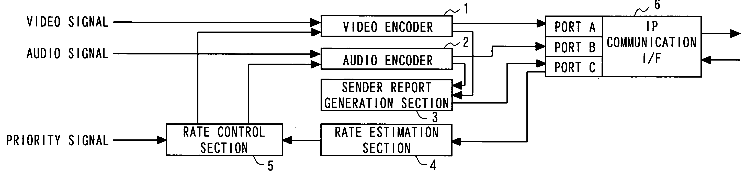
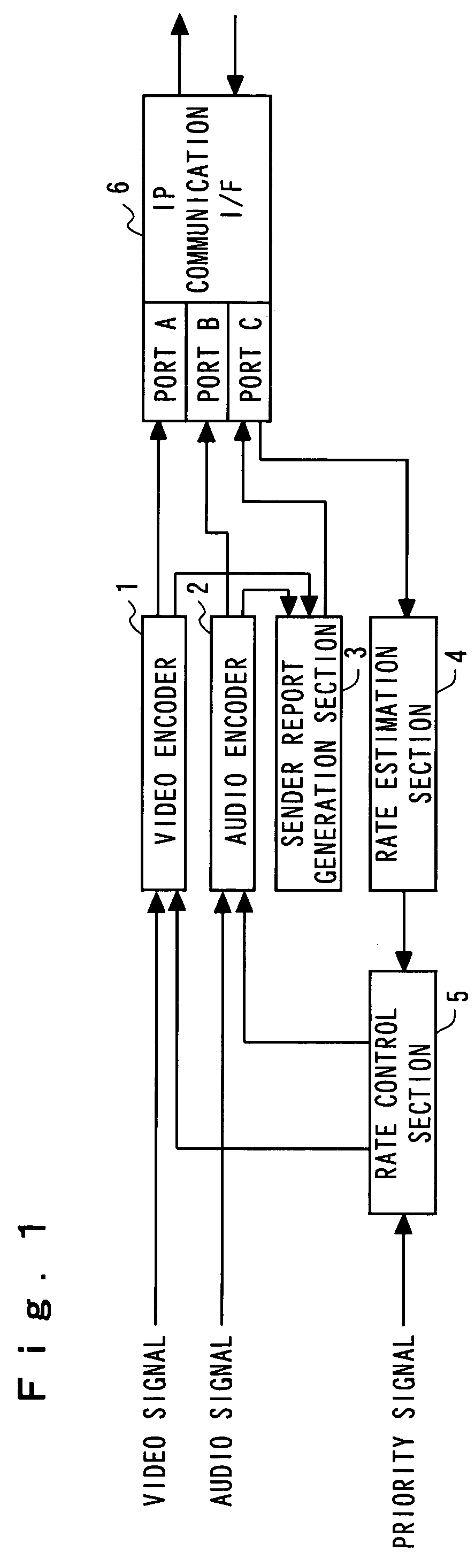
[0036]Hereafter, the present invention will be described in detail with reference to the drawings. FIG. 1 is a block configuration diagram showing an embodiment of a sender side apparatus in a moving picture compression encoding sender apparatus according to the present invention. The present apparatus may serve as a receiver side apparatus as well. In FIG. 1, however, only a configuration part concerning the sending is shown as a sending side apparatus. With reference to FIG. 1, a video signal obtained from a video device such as a camera is subjected to compression encoding in a video encoder 1. Compressed data (bit stream) generated by the video encoder 1 is packetized by using, for example, the RTP form prescribed in IETF RFC 1889. By the way, in the present invention, the packetizing form may be of any type.

[0037]At the same time, an audio signal from a microphone is subjected to compression encoding in an audio encoder 2. Compressed data (bit stream) generated by the audio enc...


PUM


Abstract

It is made possible to concretely estimate actual transmission bit rate in a frame of grasping a line state by using a report packet.Together with media packets encoded by a video encoder 1 and an audio encoder 2, a sender report packet generated by a sender report generation section 3 is sent to the transmission line. A receiver report packet is fed back from the receiver side. Each of the sender report packet and the receiver report packet includes report packets of two kinds differing in size. A rate estimation section 4 estimates transmission bit rate on the basis of round-trip delay time for the sender report packet and the receiver report packet each having a small size and round-trip delay time for the sender report packet and the receiver report packet each having a large size.

Description

BACKGROUND OF THE INVENTION[0001]1. Field of the Invention[0002]The present invention relates to a moving picture compression encoding transceiver apparatus, and in particular to such a moving picture compression encoding transceiver apparatus that transmission bit rate can be concretely estimated even in the case where transmission bit rate is altered step by step.[0003]2. Description of the Related Art[0004]In real time communication for converting a real time video signal and a real time audio signal into digital data and transmitting the digital data, control must be exercised so as to keep the encoding rate in an information source within transmission bit rate.[0005]For example, on radio transmission lines for the like of portable telephones and transmission lines of best effort type such as IP networks, it is considered that transmission bit rate varies every moment according to the congestion situation on the network. If a state in which transmission bit rate is less than the...

Claims


Application Information

Patent Timeline
Patent Type & Authority Patents(United States)
IPC IPC(8): H04J1/16H04L12/70H04L29/06H04N19/00H04N19/70
CPCH04L29/06027H04L65/80H04L65/602H04L65/762B63C11/46A63B35/12B63C9/11H04L65/1101
Inventor MIYAJI, SATOSHITAKISHIMA, YASUHIRONAKAJIMA, YASUYUKI
Owner KDDI R&D LAB INC
Why Eureka
Try Eureka