Supercharge Your Innovation With Domain-Expert AI Agents!

Tri-line power cable for electrical submersible pump

a technology of power cable and electrical submersible pump, which is applied in the direction of cables, insulated conductors, and borehole/well accessories, etc., can solve the problems that the current high temperature polymer materials may not be able to withstand high temperatures, and require the pump assembly to be pulled and replaced

Active Publication Date: 2009-11-03
BAKER HUGHES HLDG LLC
View PDF21 Cites 38 Cited by
  • Summary
  • Abstract
  • Description
  • Claims
  • Application Information

AI Technical Summary

Benefits of technology

This configuration significantly enhances the motor lead's ability to withstand high temperatures and harsh environments, preventing insulation degradation and fluid migration, thus reducing the need for premature pump assembly replacements and ensuring reliable operation.

Problems solved by technology

However, current high temperature polymer materials may not be capable of withstanding the high temperatures and harsh environments in some wells.
If the insulation degrades, a short could result that would require the pump assembly to be pulled and replaced.

Method used


Image

  • Tri-line power cable for electrical submersible pump
  • Tri-line power cable for electrical submersible pump
  • Tri-line power cable for electrical submersible pump

Examples


Embodiment Construction

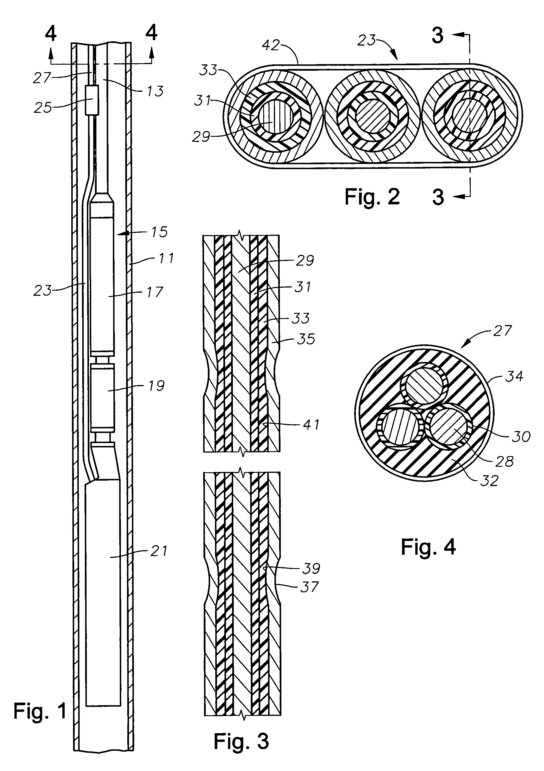
[0022]Referring to FIG. 1, a well having a casing 11 is shown. A string of production tubing 13 extends into casing 11. A pump assembly 15 is secured to the lower end of tubing 13 for pumping well fluid up tubing 13 to the surface.

[0023]Pump assembly 15 has a pump 17 of conventional design. Pump 17 may be a centrifugal pump having a large number of stages, each stage having an impeller and a diffuser. Alternately, pump 17 could be another type such as a progressing cavity pump, a gas compressor or a turbine pump. Pump 17 has a seal section 19 on its lower end that connects to a motor 21. Seal section 19 equalizes the hydrostatic pressure of fluid in casing 11 with lubricant within motor 21. Motor 21 is normally a three-phase AC motor.

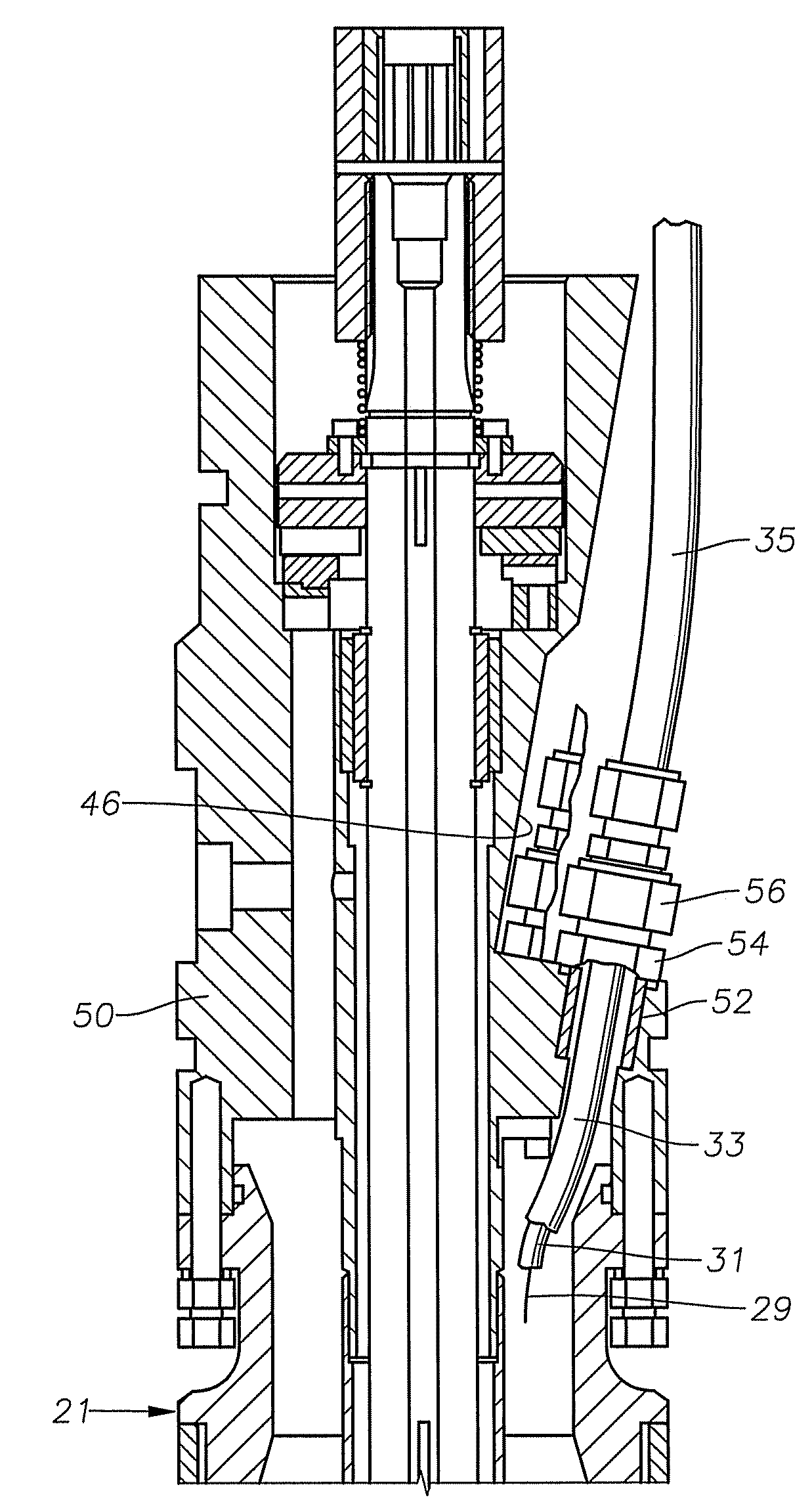
[0024]A power line comprising a motor lead 23 and a power cable 27 supplies electrical power to motor 21. Motor lead 23 has a lower end that connects to motor 21. A splice 25 joins the upper end of motor lead 23 to power cable 27 In this embodiment, pow...


PUM


Abstract

A power line for an electrical submersible pump has three metallic impermeable tubes. A single electrical conductor is located within each of the tubes. Each conductor has at least one elastomeric insulation layer surrounding it. An annular portion of the insulation layer of each of the electrical conductors is in tight contact with the tube to form a seal. The annular portions may be annular crimps formed in the tube at intervals. The annular portion could also be a continuous seal caused by swelling of the insulation layer due to contact with a hydrocarbon.

Description

FIELD OF THE INVENTION[0001]The invention relates in general to electrical submersible pump assemblies, and in particular to a power cable for supplying power to the pump motor.BACKGROUND OF THE INVENTION[0002]A common type of electrical submersible pump comprises a centrifugal pump suspended on a string of tubing within a casing of the well. The pump is driven by a downhole electrical motor, normally a three-phase AC type. A power line extends from a power source at the surface alongside the tubing to the motor to supply power.[0003]Typically the power line is made up of two sections, a motor lead and a power cable. The motor lead has a plug on its lower end that secures to a receptacle known as a “pothead” at the upper end of the electrical motor. The motor lead has three conductors that are insulated and located within a single elastomeric jacket that is extruded around the assembled insulated conductors. Metallic outer armor may wrap around the jacket of the motor lead to avoid ...

Claims


Application Information

Patent Timeline
Patent Type & Authority Patents(United States)
IPC IPC(8): F04B17/00E21B23/14
CPCE21B43/128H01B7/046F04D13/10F04D13/0693H02G15/013
Inventor TETZLAFF, STEVEN K.PARMETER, LARRY J.DOTY, ED L.COYLE, ROB A.WALLACE, THOMSON H.DALRYMPLE, LARRY V.NEUROTH, DAVID H.
Owner BAKER HUGHES HLDG LLC
Features
  • R&D
  • Intellectual Property
  • Life Sciences
  • Materials
  • Tech Scout
  • Unparalleled Data Quality
  • Higher Quality Content
  • 60% Fewer Hallucinations
Learn More