Direction finding

a direction finding and direction technology, applied in the direction of direction finders, multi-channel direction-finding systems using radio waves, radio wave direction/deviation determination systems, etc., can solve the problems of reducing affecting the service life of receivers, etc., to achieve the effect of reducing cost and bulk

Active Publication Date: 2009-11-03
QINETIQ LTD
View PDF13 Cites 52 Cited by
  • Summary
  • Abstract
  • Description
  • Claims
  • Application Information

AI Technical Summary

Benefits of technology

[0016]The invention provides the advantage of requiring only a single receiver when successive signal strengths a...

Problems solved by technology

Assuming the wavefronts have narrow bandwidth, these delays give rise solely to relative phase shifts.
This approach suffers from the problem of requiring as many receivers as there are antennas, receivers being expensive and bulky.
It is unsuitable for exampl...

Method used


Image

  • Direction finding
  • Direction finding
  • Direction finding

Examples


Embodiment Construction

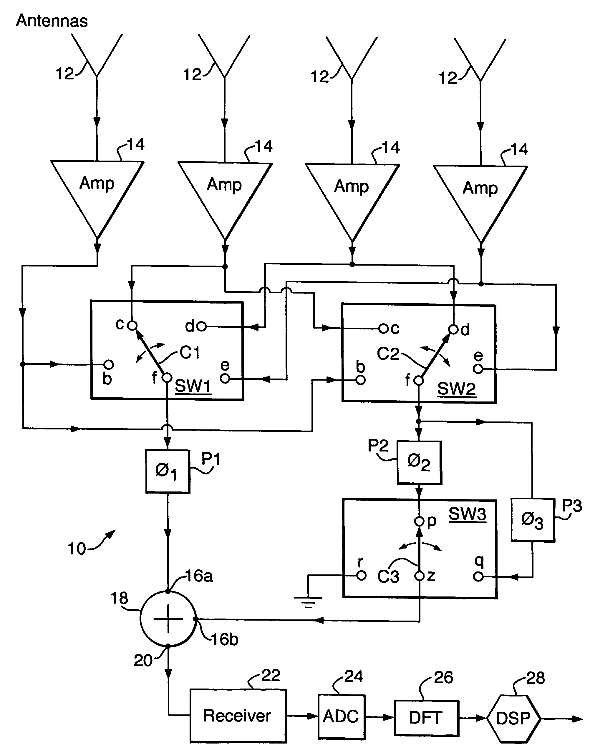
[0037]Referring to FIG. 1, a direction finding system of the invention is indicated generally by 10. As illustrated for the purposes of this example, the system 10 incorporates four antennas 12 each of which is conventional, i.e. omnidirectional. In general, as many antennas may be used as are required to detect a desired number of emitters, i.e. M antennas for M−1 emitters. Signals pass from the antennas 12 via respective buffer amplifiers 14 to first and second multipole switches SW1 and SW2, the amplifiers 12 being connected to respective input poles b, c, d and e of both switches. The multipole switches SW1 and SW2 have respective movable contacts C1, C2 which allow any of the associated input poles b to d in each case to be connected to respective output poles f.

[0038]The output pole f of the first switch SW1 is connected to a first phase shifter P1 introducing a phase shift of φ1, and the output pole f of the second switch SW2 is connected to second and third phase shifters P2...


PUM


Abstract

Direction findings by radio comprises arraigning an array of antennas, to receive signals from emitters, selecting individual antenna signals using a first multipole switch and determining, antenna signal strengths. Individual antenna signals are also selected by mutipole switch, which routes a selected signal to a third multipole switch. The third switch switches a phase shifter into and out of an antenna signal path. An adder is employed to add an antenna signal in a first signal path extending via the first multipole switch to a different antenna signal in a second signal path extending via the second and third switches. This determines combined signal strengths between pairs of antenna signals, one of which either has or has not been relatively phase shifted depending on the third switch position. Covariance matrix elements are determined from signal strengths enabling emitter bearings to be derived.

Description

BACKGROUND OF THE INVENTION[0001](1) Field of the Invention[0002]This invention relates to direction finding, and more particularly to direction finding using radio techniques.[0003](2) Description of the Art[0004]Direction finding by radio is known. In a direction finding system having a number of separate antennas, radio wavefronts reach the antennas with different delays. Assuming the wavefronts have narrow bandwidth, these delays give rise solely to relative phase shifts. For determining the directions or bearings of M−1 radio frequency (RF) emitters (M is a positive integer), a typical direction finding system employs M antennas, a respective receiver for each antenna, and processing circuitry for each receiver. The processing circuitry implements a discrete Fourier transform to divide its respective signal into frequency bins or channels. Signals are then combined in pairs, and for each channel a respective covariance matrix is constructed from which emitter bearings are estim...

Claims


Application Information

Patent Timeline
IPC IPC(8): G01S5/04G01S3/04G01S3/14G01S3/46G01S3/74
CPCG01S3/043G01S3/14G01S3/74G01S3/46
Inventor MACLEOD, MALCOLM DAVD
Owner QINETIQ LTD
Why Eureka
Try Eureka