Video-based system and method for counting persons traversing areas being monitored

a video-based system and counting system technology, applied in the field of video image processing, can solve the problems of low correlation level between, danger of losing the positive identification of figures, and low area, and achieve the effect of convenient installation and standalon

Inactive Publication Date: 2009-11-03
COUNTWISE
View PDF14 Cites 33 Cited by
  • Summary
  • Abstract
  • Description
  • Claims
  • Application Information

AI Technical Summary

Benefits of technology

[0012]Therefore, in view of the limitations of systems based on the prior art, there is need of a video-based system and method for obtaining information about people, whose end unit is integral, easily installable and standalone, to the greatest possible extent, in terms of integral independent capabilities for picture processing and data accumulation therein. Limitations on processing resources will not make it necessary to forgo reliability, and it will be possible to integrate the end units in modern communications systems (e.g.—cellular communications, the Internet and combinations of the two), such that data can be transferred to the customer easily, without his having to invest in additional communications and data processing systems.
[0013]One object of the present invention is to enable easy and convenient installation of one or more end units in a ceiling of any type (ordinary or acoustic). The structure of an end unit according to the invention is adapted for installation in a variety of ceilings, and no other infrastructure is required beyond the electricity supply. An end unit according to the invention is thus adapted to the level of a field technician, who will not have to do complicated assembly work or deal with auxiliary installations in the event that the ceiling is of a different type than what he expected.
[0015]A further object of the invention is to enable immediate processing, which is performed in a standalone processor integrally installed in the end unit itself. The end unit processes the video image produced by an internal camera installed in the end unit, and even enables parallel reception and processing of two video images arriving simultaneously from internal cameras installed in a single end unit or in two separate end units. The standalone processor installed in the end unit itself enables independence from distant external processing units, and the ability of a processor in one end unit to process two images simultaneously makes it possible to increase the area in respect of which the data processing is requested or to capture information about two areas such as for example the number of people entering and exiting a store, public area or area of interest and the number of people passing by a doorway or entry of such area. Similarly, a first camera in an end unit may cover an entryway / egress path of an area of interest, and a second camera in such same or another end unit may cover an area for example perpendicular to such entry, where passers-by walk past or cross in front of the area. A comparison may then be made between the number of persons passing through a first area being monitored, such as an entryway, and the number of people passing through a second area being monitored such as a passer-by walkway.
[0017]A further object of the invention is to enable processing as stated at a high resolution, in the critical initial stage of differentiating objects from the photographed background, and identification of the objects as images passing through the areas of interest in the photographed area. The invention does not “sacrifice” information that could represent images, and performs a preliminary identification at a high level, while reducing the likelihood of information loss and error.
[0021]A further object of the invention, in another preferred configuration thereof, is to enable the concentration of the retrieved data in a central site on the Web, allowing access to the data only to authorized customers (customer access is limited to data in respect of which the authorization was granted). The central site is able to provide data analysis and processing services for commercial purposes, thereby saving on the costs entailed in the development of independent computerization and data processing capabilities.

Problems solved by technology

However, since the samples are taken at low resolution with a homogenous scattering of the sample points, the correlation level between one sample and another of the same area is low and there is a danger of losing positive identification of figures due to the low resolution.
This system, which uses the resources of a personal computer (PC), is not capable of performing a high-resolution process of the images, which are constantly being received from several end units.
However, the addition of IR light resources and IR sensitive video means involve extra costs, making the system more cumbersome and requiring wiring and suitable power sources wherever the units are installed.
However, by decreasing the sampling resolution to fixed “cells” or “blocks” as mentioned, the system knowingly suffers from an information loss.
Thus, since the processing is made according to a net of “cells” or “blocks” having a fixed size, there is a danger that an object, which passes on the borders of two “blocks”, cannot be distinguished from the fixed background, and could not be identified as a figure.
Furthermore, the prior art systems do not integrate data collection into an overall system for client commercial purposes.
However, prior art video imaging systems, and visual imaging systems which supply information about the movement of people, do not deal with the combination of such systems with on-line communication systems.

Method used


Image

  • Video-based system and method for counting persons traversing areas being monitored
  • Video-based system and method for counting persons traversing areas being monitored
  • Video-based system and method for counting persons traversing areas being monitored

Examples


Embodiment Construction

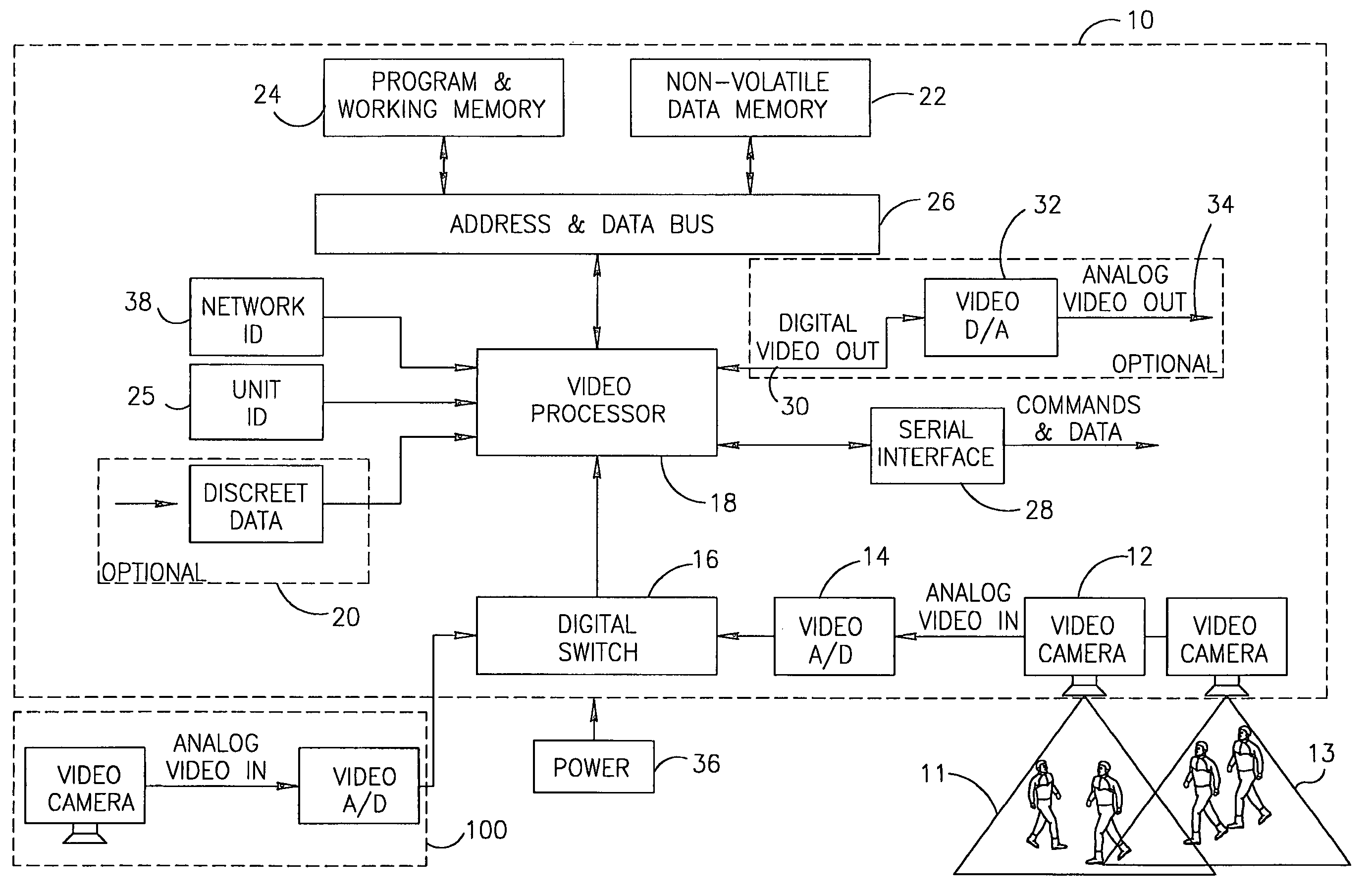
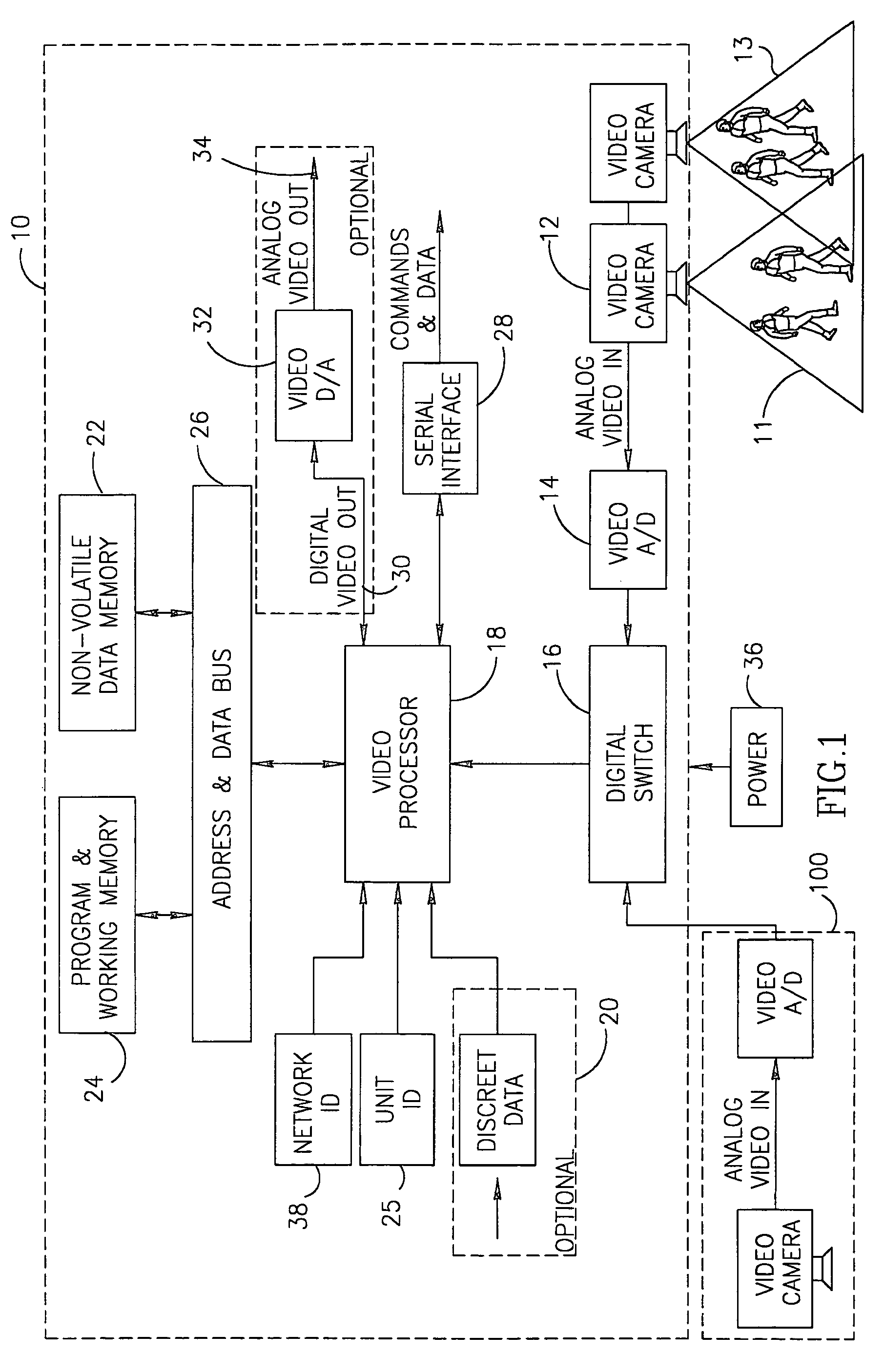
[0051]Reference is now made to FIG. 1, which is a schematic block diagram illustration of a stand alone end unit, generally designated 10, constructed and operative in accordance with a preferred embodiment of the present invention.

[0052]In accordance with an embodiment of the invention, the stand alone end unit 10 comprises two CCD type video cameras 12′ and 12″ and an A / D converter 14 for converting the analog information from the cameras to digital information. A digital switching unit 16, connects the A / D converter 14 to a video processor 18, for transferring the digital video information to the video processor 18. In some embodiments, cameras 12′ and 12″ may be positioned for example perpendicular or at other angles to each other within end unit 10 such that one such camera 12′ may capture images of for example an entryway / egress route 11 into for example a store or other space, and a second camera 12″ may capture images of a passerby route 13 that may be for example in front o...


PUM


Abstract

A video based system and method for detecting and counting persons traversing at least two areas being monitored. The method includes the steps of initialization of at least one end unit, having at least a camera, the camera producing images of at least a first area being monitored and a second area being monitored, digitizing the images and storing the digitized images in a non-volatile memory unit and a working memory unit; detecting potential persons in the images; comparing the digitized images of objects detected in the first area and second area being monitored with digitized images stored in the working memory unit to determine whether the detected object is a new figure in such area or whether the detected object is a known figure that has remained within such area and to determine that a figure which was not detected has left such area; incrementing a counter for such area with an indication of the number of persons that have passed through such area, and comparing the number of persons passing through a first area with the number of persons passing through a second area.

Description

CROSS REFERENCE TO RELATED APPLICATIONS[0001]The present application is a continuation in part of prior patent application Ser. No. 09 / 481,447 filed on Jan. 13, 2000 now U.S. Pat. No. 6,697,104 entitled “A Video-Based System and Method For Detecting and Counting Persons Traversing an Area Being Monitored”, and incorporated herein by reference in its entirety.FIELD OF THE INVENTION[0002]The invention relates generally to video image processing and more particularly to an apparatus, system and method for obtaining and processing information about the quantity and the direction of movement of people in crowded areas using video image processing.BACKGROUND OF THE INVENTION[0003]Monitoring the movement of people entering and leaving major public areas, such as malls, shopping areas, chain-stores, casinos, airports, bus and train stations and sport facilities provides significant and valuable information to the management of these areas.[0004]For example, information regarding the number ...

Claims


Application Information

Patent Timeline
Patent Type & Authority Patents(United States)
IPC IPC(8): H04N7/18H04N9/47G06K9/00G07C9/00G08B13/194
CPCG06K9/00369G06K9/00778G07C9/00G08B13/19656G08B13/19606G08B13/19619G08B13/19632G08B13/19602G06V40/103G06V20/53
Inventor LEV-RAN, ILANTOPAZ, DOV
Owner COUNTWISE
Why Eureka
Try Eureka