Joint structure of electric wire, stator of rotary electric machine, method for manufacturing the same

a technology of electric wire and stator, which is applied in the direction of windings, dynamo-electric components, connections, etc., can solve the problems of achieve the effect of rationalizing the joining work and reducing the likelihood of joining face portion peeling

Active Publication Date: 2009-11-10
HITACHI LTD
View PDF10 Cites 8 Cited by
  • Summary
  • Abstract
  • Description
  • Claims
  • Application Information

AI Technical Summary

Benefits of technology

[0012]According to another aspect of the present invention constructed as above, since joined faces of the joined face portions at the tips of the conductors with insulating coatings removed confront each other, it is not necessary to keep the two pushed against each other with a strong force during the joining work. Besides, it is possible to diminish the likelihood of peeling-off of the joined face portion caused by spring-back after joining. As a result, not only the rationalization of the joining work can be attained, but also the reliability of the joined state of the joined face portion is improved and so are the productivity and reliability of, for example, the stator of a rotary electric machine.

Problems solved by technology

Besides, it is possible to diminish the likelihood of peeling-off of the joined face portion caused by spring-back after joining.

Method used


Image

  • Joint structure of electric wire, stator of rotary electric machine, method for manufacturing the same
  • Joint structure of electric wire, stator of rotary electric machine, method for manufacturing the same
  • Joint structure of electric wire, stator of rotary electric machine, method for manufacturing the same

Examples


Embodiment Construction

[0044]Embodiments of the present invention will be described hereinunder with reference to the drawings.

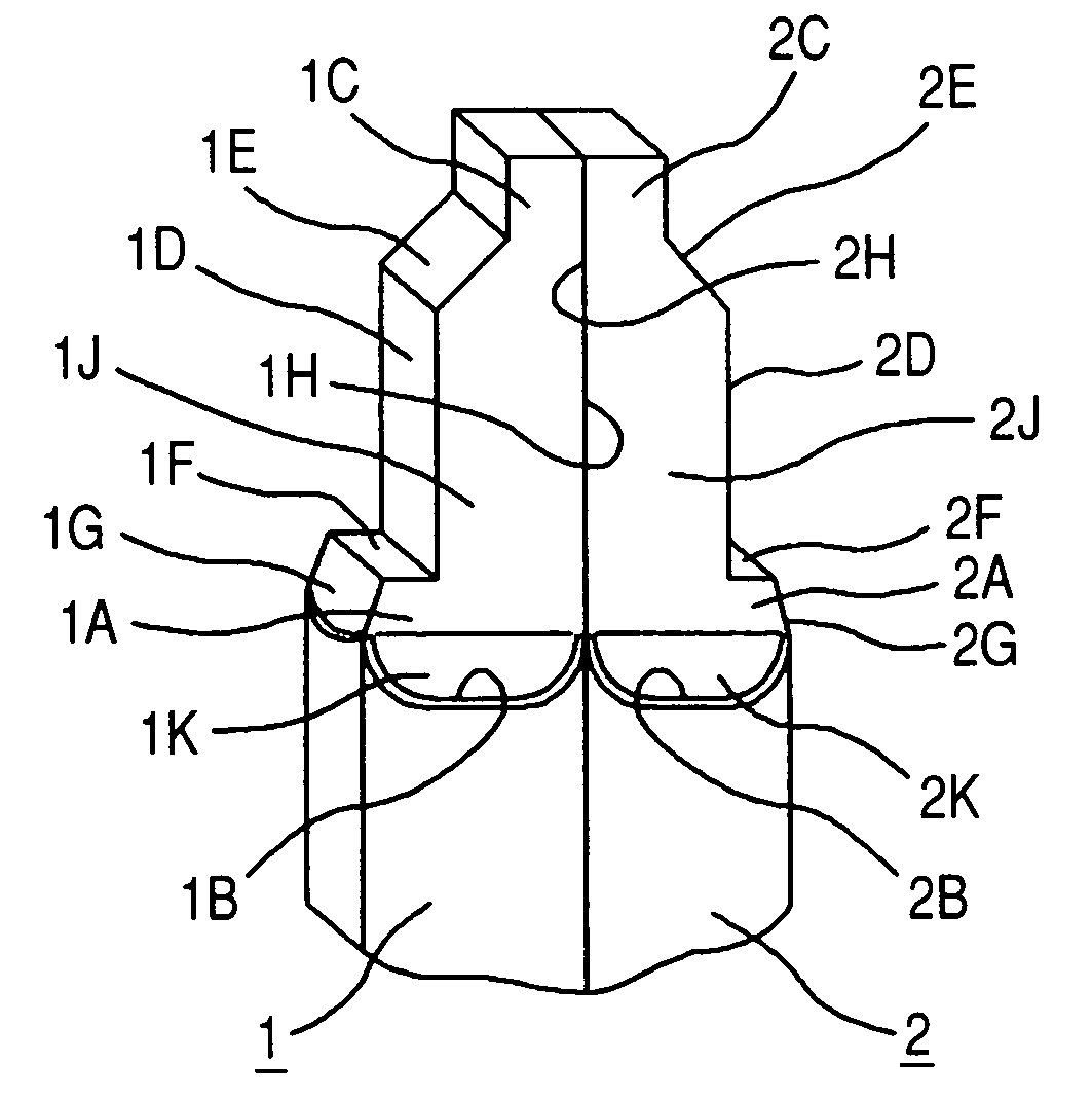
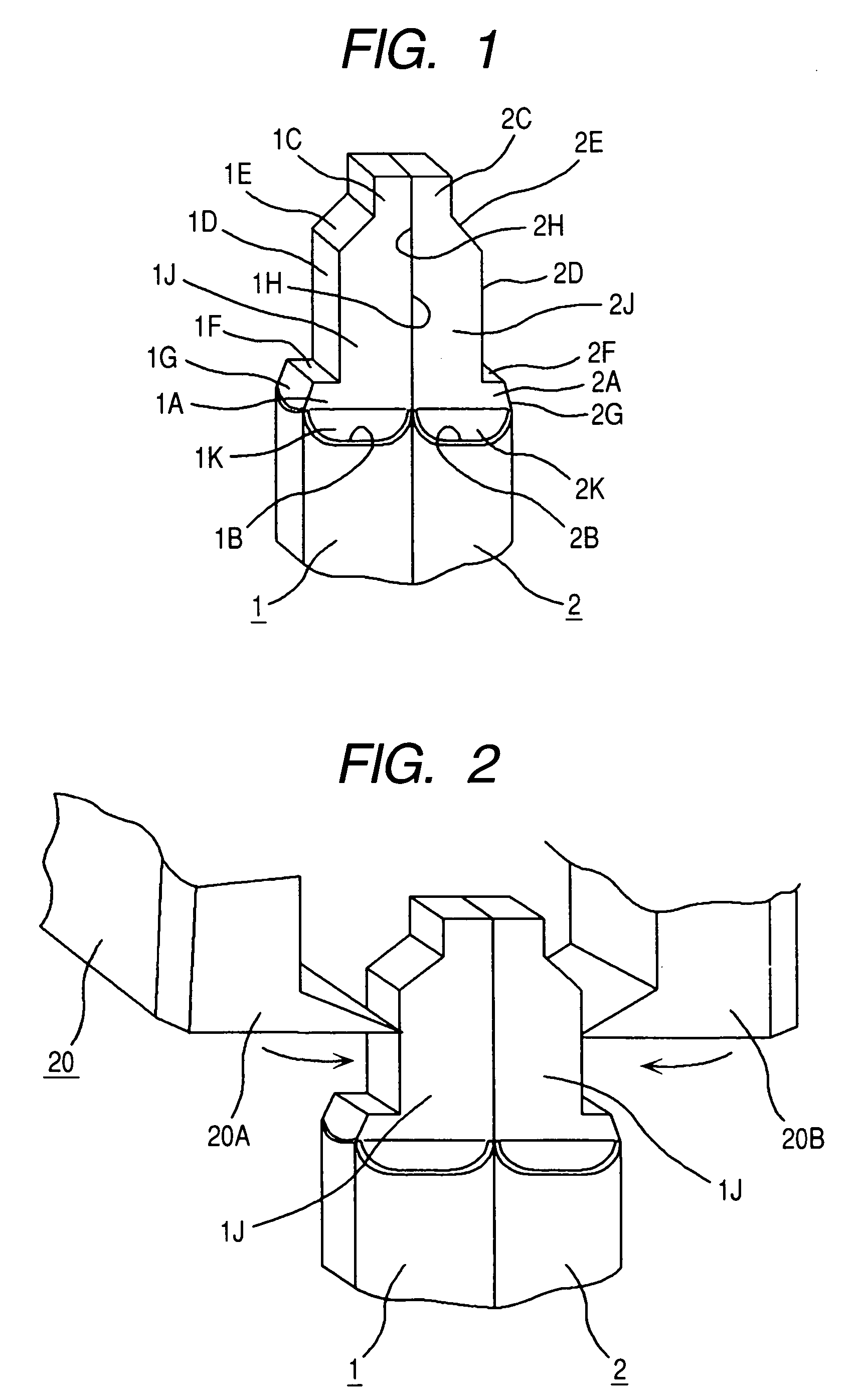
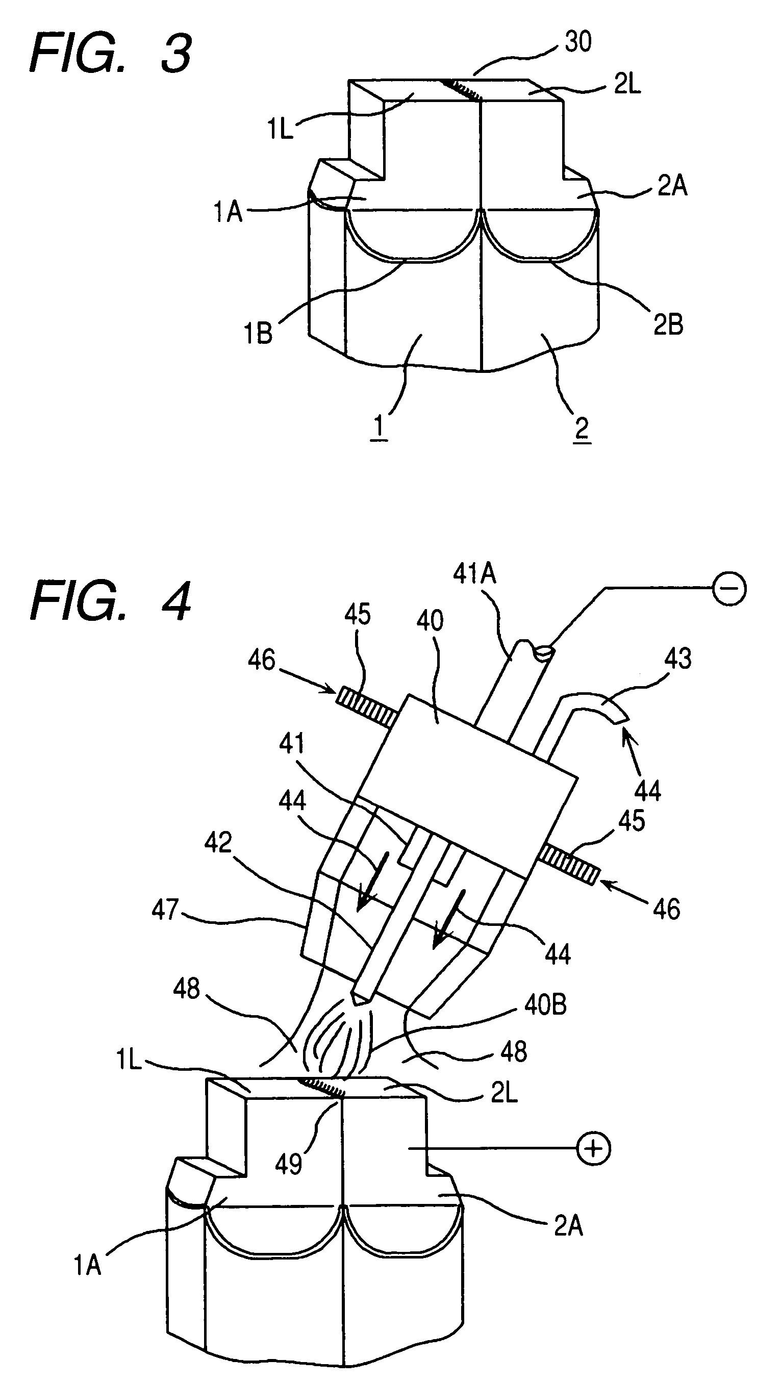
[0045]FIG. 1 is an enlarged perspective view showing a connection between electric wires (joint conductors) to which the present invention is applied.

[0046]Electric wires (joint conductors) 1 and 2 respectively comprise conductors 1A and 2A of a rectangular section coated and insulated with enamel coatings 1B and 2B.

[0047]The enamel coatings 1B and 2B are chipped off at tips of the electric wires (joint conductors) 1 and 2 to form, at the tips, projecting portions 1C and 2C which are the smallest in sectional area. The small projecting portions 1C and 2C function as cutting portions when cutting a single long conductor (a detailed description will be given later) to form a conductor piece of a required length. Sectional area portions of a medium size, which function as welding portions 1D and 2D, are formed between the small projecting portions 1C, 2C and the enamel coatings 1B, 2...


PUM

PropertyMeasurementUnit
electricaaaaaaaaaa
areaaaaaaaaaaa
shapeaaaaaaaaaa

Abstract

When electric wires (joint conductors) are disposed adjacent each other in a peeled state of coatings, a gap corresponding to the total thickness of both conductors' insulating films as skin layers is formed between end joined face portions of the conductors. The gap becomes larger because the conductors are tapered. Therefore, the adhesion between both conductors is impaired, with a consequent fear of occurrence of joining imperfection. In opposed joined face portions of electric wires (joint conductors), the conductors are deformed from the tips of their axes to the joined face side in such a manner that exposed portions at the tips of the conductors and insulating film faces located in the vicinity thereof are flush with each other or the exposed portions are projected. The gap formed between the electric wires (joint conductors) can be diminished, whereby the reliability of connection is improved and it becomes easier to perform the work of joint conductors, with the result that the productivity of a stator of a rotary electric machine such as an AC generator for a vehicle could be improved.

Description

CLAIM OF PRIORITY[0001]The present application claim priority from Japanese application serial No. 2005-150316, filed on May 24, 2005, the content of which is hereby incorporated by reference into this application.FIELD OF THE INVENTION[0002]The present invention relates to a stator of a rotary electric machine such as, for example, an AC generator for a vehicle and a method for manufacturing the same, as well as a joint structure of electric wires and a method for manufacturing the same.BACKGROUND OF THE INVENTION[0003]According to a known electric wire, an end portion of an electric wire (a joint conductor) which end portion extends over a predetermined range from a tip of the wire is plastically deformed so that a sectional area thereof becomes smaller than that of a main portion of the conductor, and the wire is constructed so that the main portion and a part of the end portion near the main portion are coated uniformly with an insulating film, then two such electric wires (join...

Claims


Application Information

Patent Timeline
Patent Type & Authority Patents(United States)
IPC IPC(8): H02K3/50H02K15/00H02K3/04
CPCH02K3/12H02K15/0081H02K15/064H02K15/0428Y10T29/49201Y10T29/49009
Inventor SAKAI, TAKESHIMORI, YOSHIMIKIMURA, YASUHIKOHONMA, MASAHIKOISHIKAWA, FUMINORI
Owner HITACHI LTD
Why Eureka
Try Eureka