Knuckle arm

a technology of knuckle arms and knuckles, which is applied in the field of knuckle arms, can solve the problems of large spring force that is difficult to overcome, high manufacturing and design costs of knuckle arms, etc., and achieve the effect of reducing manufacturing costs and simple design

Inactive Publication Date: 2009-11-17
ASIA OPTICAL INT LTD
View PDF14 Cites 15 Cited by
  • Summary
  • Abstract
  • Description
  • Claims
  • Application Information

AI Technical Summary

Benefits of technology

[0010]An object of this invention is to provide a knuckle arm that has a small number of components and a simple design so as to reduce the manufacturing costs thereof.
[0011]Another object of this invention is to provide a knuckle arm that is convenient to assemble.

Problems solved by technology

(1) The knuckle arm 10 has a substantial number of components, and therefore is bulky.
(2) There is a need for high precision during manufacture of the cam edges 131, 141 of the bottom and top cam sliding seats 13, 14. The processes required to achieve such high precision, particularly in consideration of the fact that the shapes of the cam edges 131, 141 are different, ultimately result in high manufacturing and design costs of the knuckle arm 10.
(3) During assembly, it is necessary to press the compression spring 15 toward the bottom sliding seat 13 just before the top pivot rod 18 is inserted into the connecting seat 12 and the lifting seat 16. The compression spring 15 has a large spring force that is difficult to overcome.

Method used


Image

  • Knuckle arm
  • Knuckle arm
  • Knuckle arm

Examples


Embodiment Construction

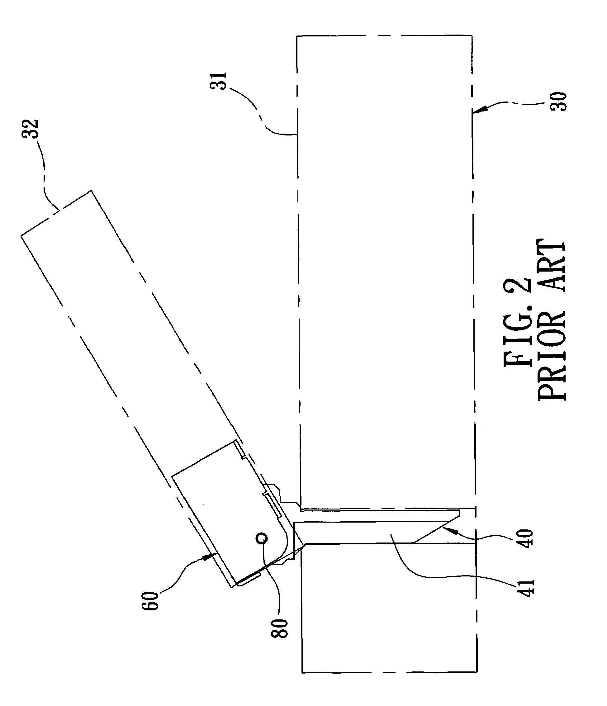
[0025]Referring to FIG. 2, the preferred embodiment of a knuckle arm according to this invention is disposed between a machine body 31 and a top cover 32 of an office machine 30, such as a copier, or a scanner. When the office machine 30 is a copier, the top cover 32 may serve as an auto document feeder.

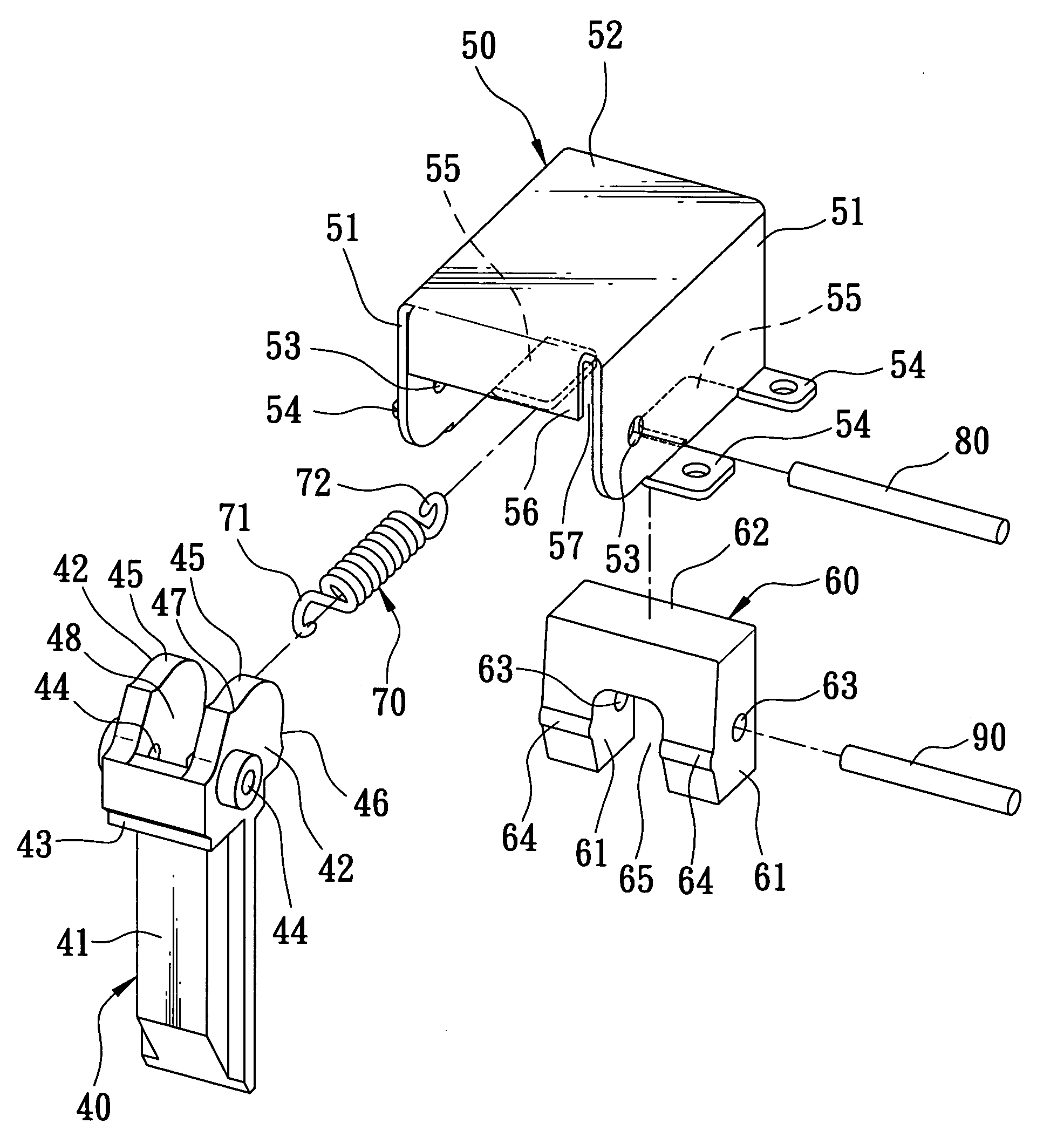
[0026]Referring to FIGS. 3 and 4, the knuckle arm includes a mounting seat 40, a connecting seat50 connected pivotally to the mounting seat 40, a sliding seat 60 disposed movably within the connecting seat 50, and a resilient member 70 disposed between the mounting seat 40 and the sliding seat 60.

[0027]The mounting seat 40 is made of a plastic material, and includes a mounting block 41 disposed fixedly on the machine body 31, a pair of first and second pivot blocks 42 extending integrally from the mounting block 41 and spaced apart from each other by a mounting groove 48, and a positioning block 43 interconnecting the first and second pivot blocks 42. Each of the first and second piv...


PUM


Abstract

A knuckle arm is connected to a machine body and a top cover of a machine, and includes a mounting seat, a connecting seat, a sliding seat, and a resilient member. The mounting seat includes a mounting block disposed fixedly on the machine body, and a pivot block extending integrally from the mounting block and having a cam edge. The connecting seat is connected pivotally to the pivot block of the mounting seat, and is attached to the top cover. The sliding seat is disposed slidably within the connecting seat, and has an integral projection. The resilient member is disposed between the mounting seat and the sliding seat, and biases the sliding seat to move toward the mounting seat so as to keep the projection of the sliding seat in contact with the cam edge of the mounting seat.

Description

CROSS-REFERENCE TO RELATED APPLICATION[0001]This application claims priority of Taiwanese Application No. 094132086, filed on Sep. 16, 2005.BACKGROUND OF THE INVENTION[0002]1. Field of the Invention[0003]This invention relates to a part of an office machine, and more particularly to a knuckle arm that interconnects a machine body and a top cover of an office machine.[0004]2. Description of the Related Art[0005]Two knuckle arms are typically disposed between a top cover and a machine body of an office machine, such as a copier, or scanner, for use in the opening and closing of the top cover relative to the machine body. Referring to FIG. 1, a conventional knuckle arm 10, which is disclosed in U.S. Pat. No. 6,456,365, is shown to include a mounting seat 11 fixed on a machine body 21 of an office machine 20, a connecting seat 12 disposed pivotally on the mounting seat 11, a bottom cam sliding seat 13 disposed slidably within the connecting seat 12, a top cam sliding seat 14 disposed sl...

Claims


Application Information

Patent Timeline
Patent Type & Authority Patents(United States)
IPC IPC(8): E05F1/08
CPCE05F1/1276Y10T16/5323Y10T16/5383E05Y2201/638E05Y2900/608
Inventor JING, MAO-SHENG
Owner ASIA OPTICAL INT LTD
Why Eureka
Try Eureka