Apparatus and methods for ventilation of solar roof panels

a technology of solar panels and roofs, applied in ventilation systems, lighting and heating apparatus, heating types, etc., can solve problems such as performance and efficiency decline, and achieve the effects of reducing the temperature inside the attic, and improving the efficiency of the panels

Active Publication Date: 2009-11-17
ODANIELS LLC
View PDF21 Cites 69 Cited by
  • Summary
  • Abstract
  • Description
  • Claims
  • Application Information

AI Technical Summary

Benefits of technology

[0010]A solar panel typically comprises semiconductor layers that react to photon inputs by generating a flow of electrons. Such devices are often designed to operate within an optimum temperature envelope. If the temperature is too high, or if the solar panels become too hot, their performance and efficiency can decline. The presently disclosed embodiments seek to overcome this problem by providing for ventilation airflow in and around the installed solar panels, and of the space between the solar panels and the portion of the roof below the solar panels, thus improving the efficiency of said panels in certain temperature conditions. In some aspects of the invention, radiant barriers are also provided to reduce the temperature inside the attic. In further aspects, fans are also provided in order to assist the ventilation.

Problems solved by technology

If the temperature is too high, or if the solar panels become too hot, their performance and efficiency can decline.

Method used


Image

  • Apparatus and methods for ventilation of solar roof panels
  • Apparatus and methods for ventilation of solar roof panels
  • Apparatus and methods for ventilation of solar roof panels

Examples


Embodiment Construction

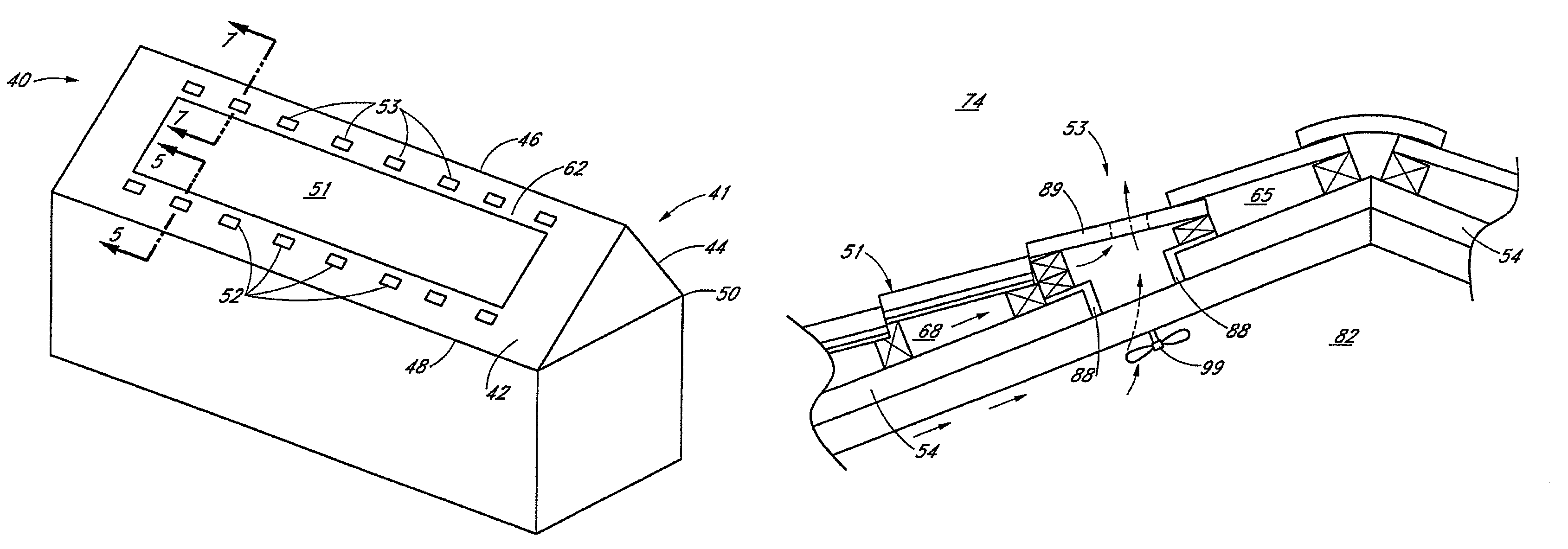
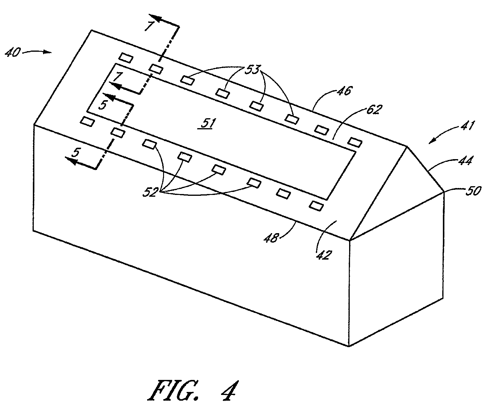
[0029]FIG. 4 is a perspective view of a building 40 having a roof 41 in accordance with one embodiment of the present invention. The roof 41 includes roof fields or portions 42 and 44, a ridge 46, and eaves 48 and 50. A field of solar panels 51 is provided within the roof portion 42. While not shown, an additional field of solar panels 51 can be provided within the roof portion 44. The solar panel field 51 can comprise a plurality of solar panels, or alternatively only one larger panel. It will also be understood that multiple contiguous fields of solar panels could be provided within each roof portion 42 and 44, instead of just one contiguous field 51 as shown. As used herein, a solar panel “field” refers to an arrangement of one or more solar panels along a planar or possibly curved surface. Preferably, the one or more solar panels substantially mimic the appearance of the remainder of the roof portion 42.

[0030]The illustrated roof 41 includes a first plurality of roof field vents...


PUM


Abstract

A roof portion including solar roof panels and field vents is disclosed. The roof portion includes a sloped roof deck and a cover layer spaced above the roof deck to form a gap between the roof deck and the cover layer. The cover layer includes a layer of cover elements, and a field of one or more solar panels generally within the layer of cover elements. The cover layer also includes a first plurality of field vents positioned within the cover layer substantially immediately below the solar panel field. The cover layer further includes a second plurality of field vents positioned within the cover layer substantially immediately above the solar panel field. The field vents permit airflow between the gap and the atmosphere above the roof.

Description

CLAIM FOR PRIORITY[0001]This application claims the priority benefit under 35 U.S.C. § 119(e) of Provisional Application Ser. No. 60 / 780,014, filed Mar. 6, 2006. The full disclosure of this priority application is incorporated herein by reference.BACKGROUND OF THE INVENTION[0002]1. Field of the Invention[0003]This application relates generally to roof ventilation systems, and specifically to ventilation systems for roofs employing solar panels.[0004]2. Description of the Related Art[0005]A roof of a building typically includes roof vents that ventilate the region directly underneath the roof, which is ordinarily the building's attic space. Ventilation of the attic is important in keeping the building temperature from rising to undesirable levels. A variety of different types of roof vents exist, such as field vents, eave vents, ridge vents, soffit or undereave vents, and the like. Of particular interest for the present application is a field vent, which is a vent positioned within t...

Claims


Application Information

Patent Timeline
Patent Type & Authority Patents(United States)
IPC IPC(8): F24F7/02E04B7/00E04D13/18
CPCE04D13/008E04D13/17H02S20/23F24F7/02Y02B10/12Y10S454/90F24F7/025Y02B10/10Y02E10/50
Inventor DANIELS, GREGORY S.
Owner ODANIELS LLC
Why Eureka
Try Eureka