
System and method for performing spinal fusion

Inactive Publication Date: 2009-11-17
NUVASIVE
View PDF189 Cites 116 Cited by
  • Summary
  • Abstract
  • Description
  • Claims
  • Application Information

AI Technical Summary

Benefits of technology

[0011]By orienting the bone implants in this fashion, the present invention is capable of restoring and maintaining adequate disc height notwithstanding a general shortage of single graft bone implants having sufficient height and strength to effect fusion. That is to say, by placing bone grafts of reduced overall size on their “sides” (with the graft implant rotated approximately 90 degrees such that the dimension that would ordinarily be the width now constitutes the height) they may still be useful. More importantly, the grafts accomplish this without jeopardizing their structural integrity or stability once implanted, since they are disposed a distance from one another so as to provide, in essence, a base or “stance” of increased dimension.
[0013]Inserting two, or more, allograft implants simultaneously creates a sufficient combined area to provide stability and sufficient force distribution to withstand the compressive stresses in the spine. Additionally, the monolithic grafts do not risk the separation of layers possible in implants constructed from multiple laminations. The allograft implants are also conducive to natural fusion, germane to the human body and do not hinder post-operative imaging.

Problems solved by technology

The discs may become damaged due to injury or age and symptoms of a damaged disc may include severe pain, numbness or muscle weakness.
A problem exists, however, in that cadaveric bone (used to produce bone allograft implants) is oftentimes of insufficient dimension to produce grafts of adequate height, especially in cervical applications.
However, the general reduction in the “femur thickness” dimension attributable to age effectively limits and creates a general shortage in the amount of cadaveric bone that can be used in such cervical applications because it is of insufficient dimension to restore disk height.
Efforts to overcome the size limitation have been undertaken (such as providing bone implants formed from multiple laminations), but have failed or are lacking in various respects.

Method used


Image

  • System and method for performing spinal fusion
  • System and method for performing spinal fusion
  • System and method for performing spinal fusion

Examples


Embodiment Construction

[0023]Illustrative embodiments of the invention are described below. In the interest of clarity, not all features of an actual implementation are described in this specification. It will of course be appreciated that in the development of any such actual embodiment, numerous implementation-specific decisions must be made to achieve the developers' specific goals, such as compliance with system-related and business-related constraints, which will vary from one implementation to another. Moreover, it will be appreciated that such a development effort might be complex and time-consuming, but would nevertheless be a routine undertaking for those of ordinary skill in the art having the benefit of this disclosure. The systems disclosed herein boast a variety of inventive features and components that warrant patent protection, both individually and in combination.

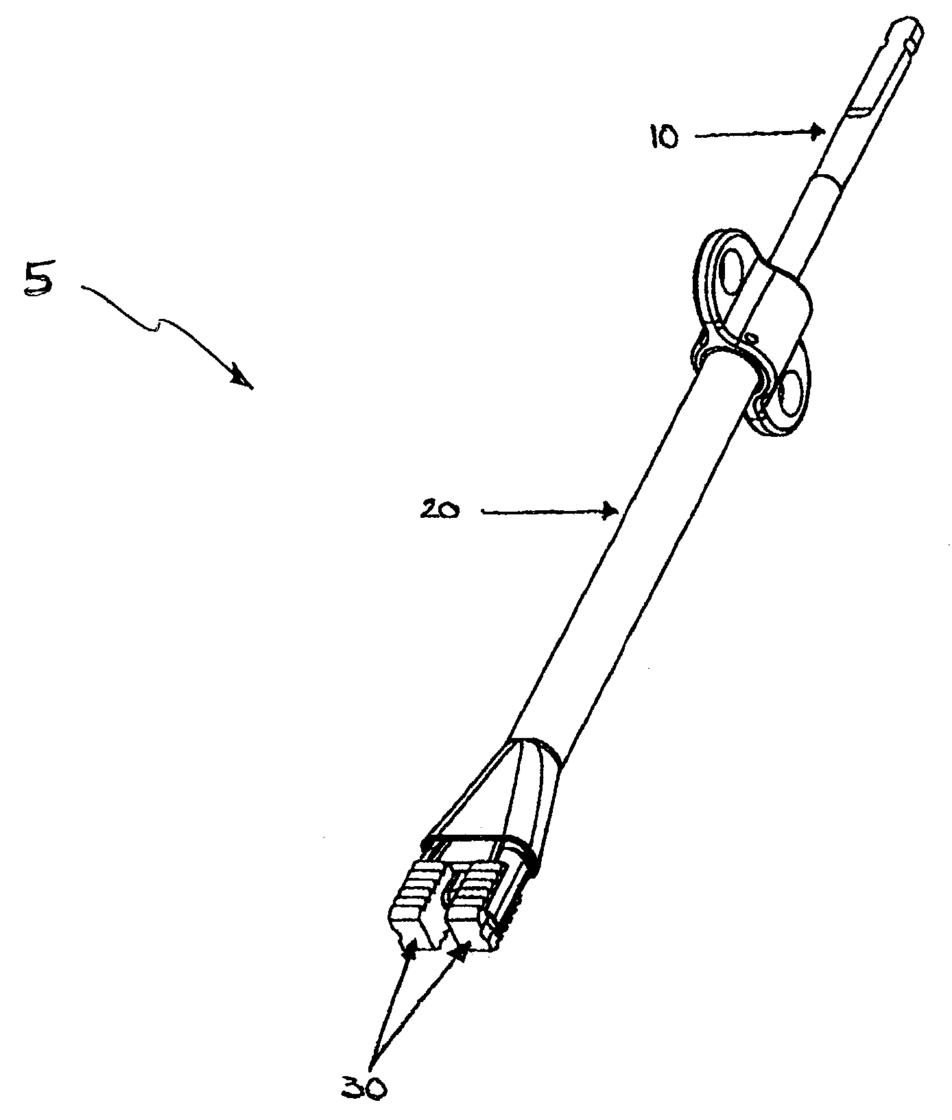
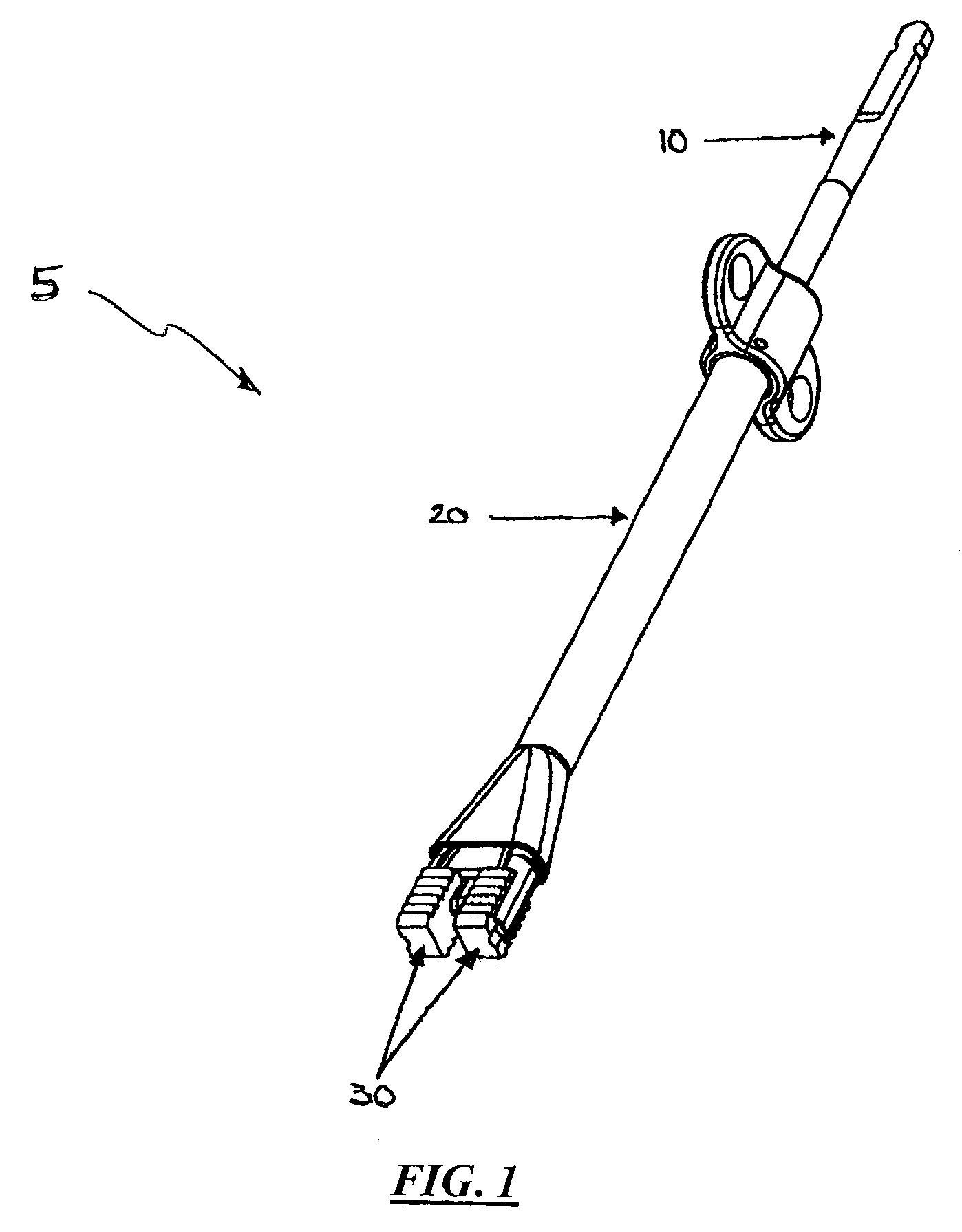
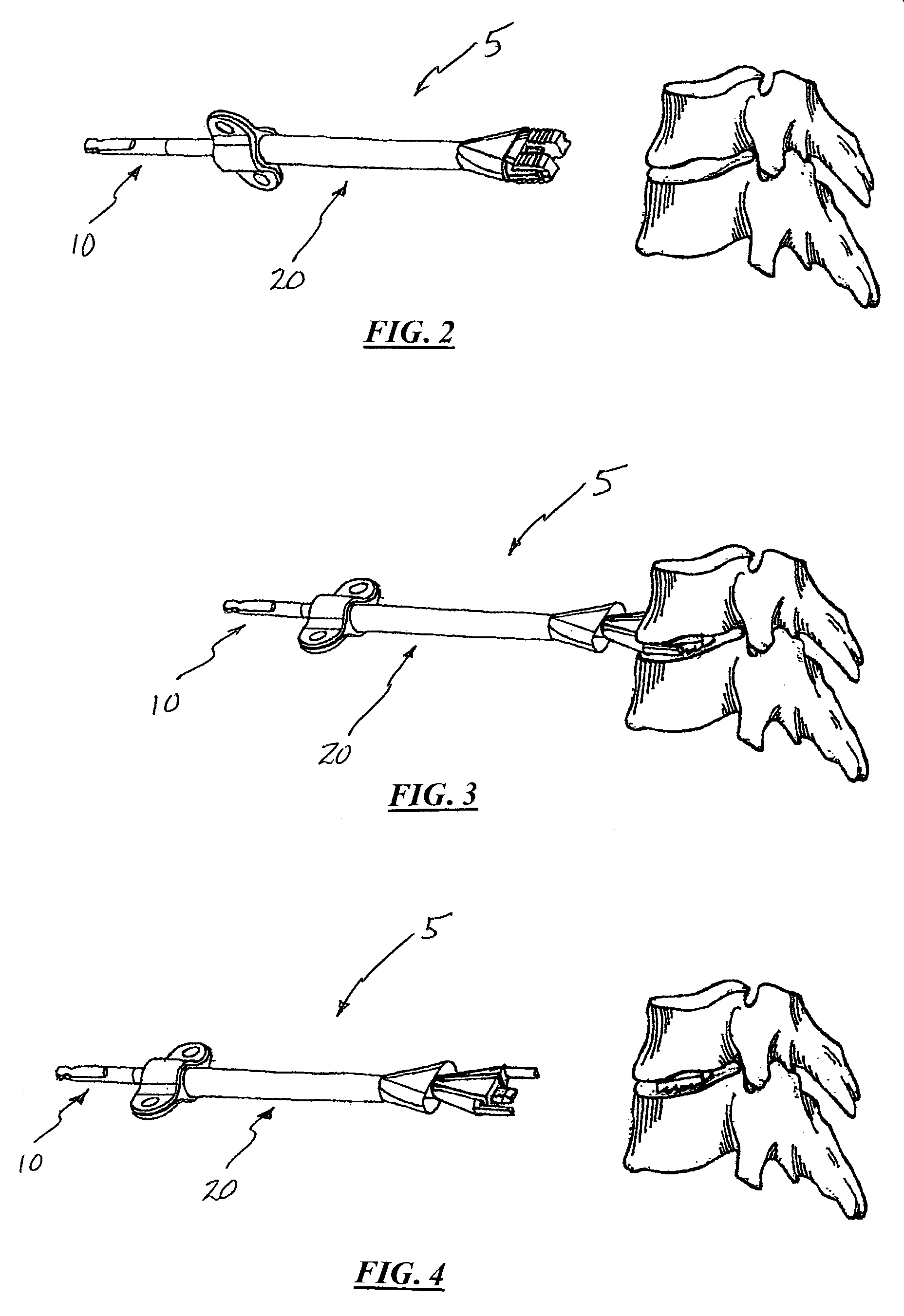
[0024]FIG. 1 illustrates a system 5 for performing spinal fusion according to one aspect of the present invention. The system 5 ...


PUM


Abstract

A system and associated methods for performing spinal fusion, involving the use of a graft holder assembly, a locking assembly, and a pair of bone graft implants to simultaneously introduce the bone graft implants into a disc space to thereafter effect spinal fusion.

Description

CROSS-REFERENCES TO RELATED APPLICATIONS[0001]The present application is a US Non-Provisional Patent Application of and claims the benefit of priority from commonly owned and co-pending U.S. Provisional Patent Application Ser. No. 60 / 389,232 (filed Jun. 15, 2002), the entire contents of which is hereby expressly incorporated by reference into this disclosure as if set forth fully herein.BACKGROUND OF THE INVENTION[0002]I. Field of the Invention[0003]The present invention relates to medical devices and methods generally aimed at spinal surgery. In particular, the disclosed system and associated method relate to performing spinal fusion.[0004]II. Discussion of the Prior Art[0005]Spinal discs serve to cushion and stabilize the spine in addition to distributing stress and damping cyclic loads. The discs may become damaged due to injury or age and symptoms of a damaged disc may include severe pain, numbness or muscle weakness. Fusion is one method of reducing the magnitude of the symptom...

Claims


Application Information

Patent Timeline
IPC IPC(8): A61B17/58
CPCA61F2/447A61F2/4611A61F2/28A61F2002/2817A61F2002/2839A61F2002/30156A61F2310/00359A61F2002/30904A61F2002/30971A61F2002/448A61F2002/4627A61F2002/4628A61F2230/0023A61F2002/3082
Inventor VALENTINE, KEITHMILES, PATARAMABULA, JAREDCASTLEBERRY, JEFFHILDEBRAND, BRYAN D.MARTINELLI, SCOT
Owner NUVASIVE
Learn More