
Device and method for manufacturing thin films

a manufacturing device and thin film technology, applied in the direction of coatings, chemical vapor deposition coatings, metallic material coating processes, etc., can solve the problems of shortening the maintenance cycle of the mass-production device, loss of the balance and loss of the concentric exhaust port balance, etc., to achieve good film thickness distribution, composition distribution and film-forming rate, and stable and continuous formation.

Active Publication Date: 2009-11-17
ULVAC INC
View PDF43 Cites 17 Cited by
  • Summary
  • Abstract
  • Description
  • Claims
  • Application Information

AI Technical Summary

Benefits of technology

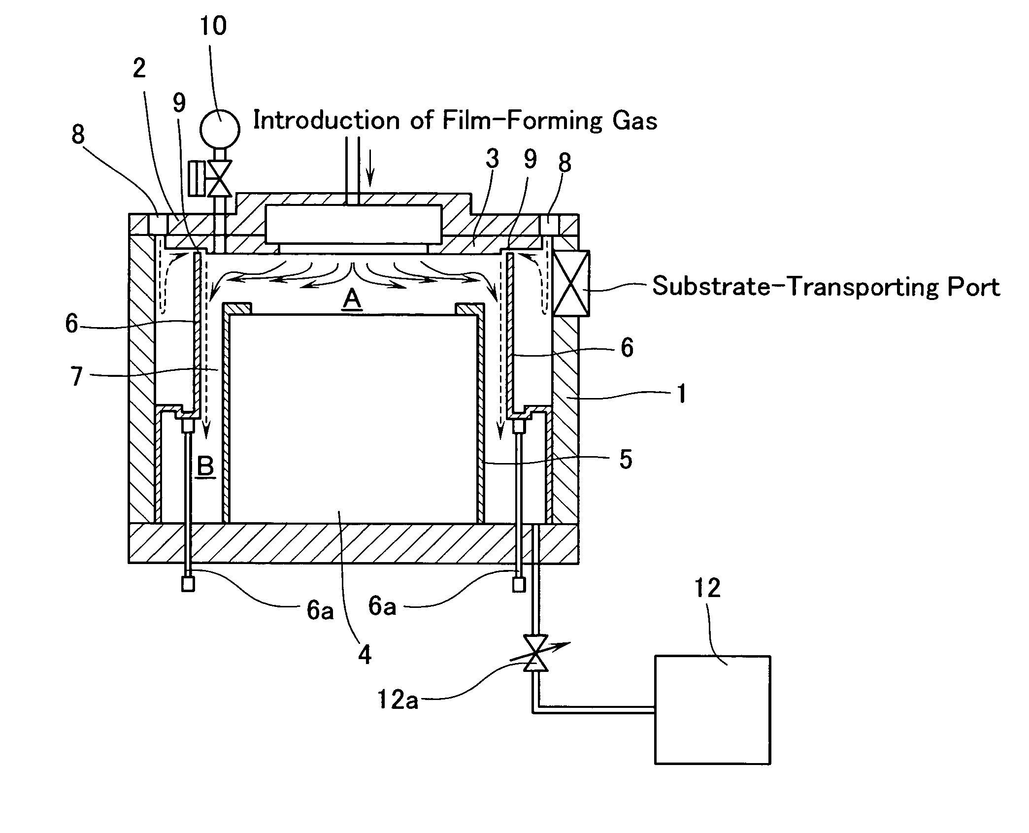
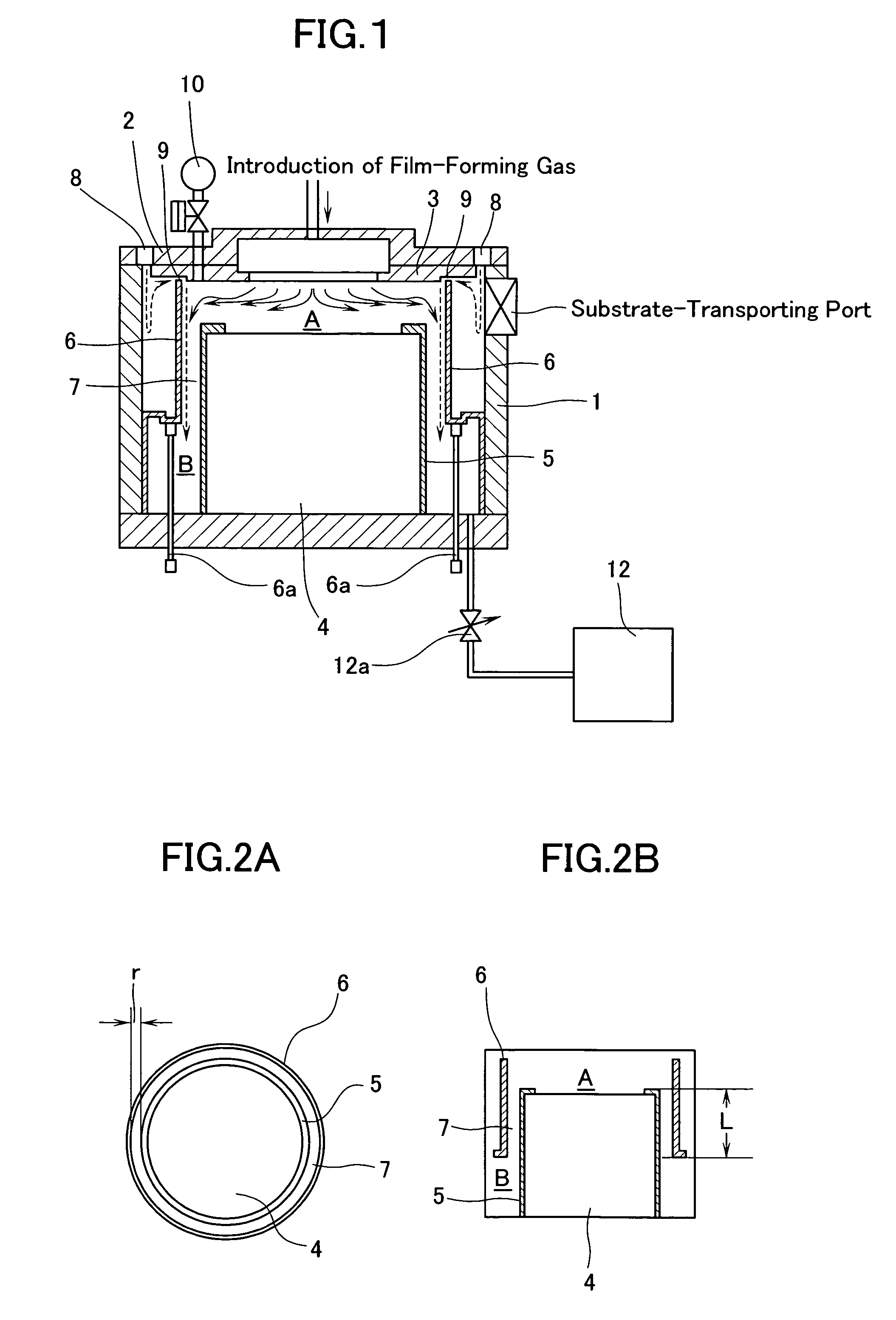
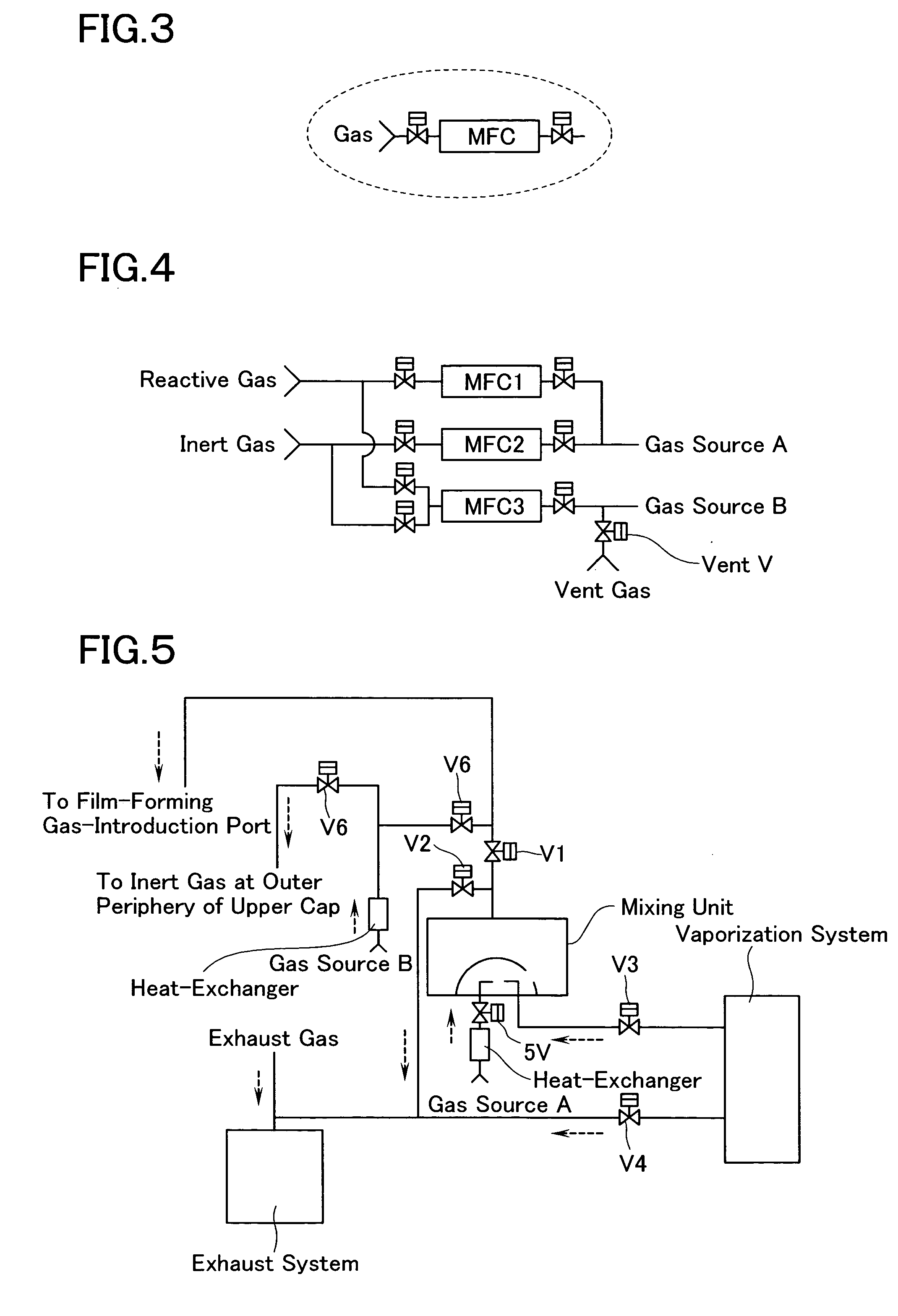
[0014]Accordingly, it is in general an object of the present invention to solve the foregoing problems associated with the foregoing conventional techniques and more specifically, it is an object of the present invention to provide a thin film-manufacturing device and a thin film-manufacturing method which are excellent in the mass-production ability and productivity, which permit the stable and continuous production of films over a long period of time while reproducing a good film thickness distribution, a good compositional distribution and a high film-forming rate and controlling the number of particles generated during the film-formation to a lower level. Moreover, the thin film-manufacturing device has a system which permits the down flow vent subsequent to the down flow state of the device without interruption of any gas supply when venting the interior of the device.

Problems solved by technology

In the conventional thin film-manufacturing device, in particular, such a device equipped with a mechanism for elevating or ascending and descending a substrate-supporting stage, the stage is moved or pulled along the exhaust direction upon the evacuation of the device (film-forming vessel) due to the play of the elevating mechanism and this accordingly leads to the loss of the balance of a concentric exhaust port (a path for evacuation) about the stage, which has been adjusted in advance under the atmospheric pressure.
This lower space is one for realizing the required isotropic evacuation, but the stage is pulled along the exhaust direction upon the evacuation of the device due to the play of the elevating mechanism as has been discussed above and this in turn leads to the loss of the balance of the concentric exhaust port, which has been adjusted in advance under the atmospheric pressure.
This becomes a source of particles and this in turn shortens the maintenance cycle of the mass-production device.
However, a shower nozzle is a movable part (see, for instance, Japanese Un-Examined Patent Publication Hei 9-316644 (Claims, Examples)) and therefore, an unnecessary space is formed around the shower head and convection or a turbulent flow may be generated therein.
This also serves as a source of particles and in turn makes the maintenance cycle of the mass-production device short.
However, there has not yet been developed any structure which permits the satisfactory dissipation of heat from the surface of the shower head or the satisfactory heat-exchange.
This in turn results in the deposition of raw materials and becomes a cause of particle generation.
As has been well known in the art, SUS is highly inferior in the heat conduction (the heat conductivity of SUS is about 16 W / mK, while that of Al is about 240 W / mK) and it is thus quite insusceptible to heat transfer.
However, alumina is insufficient in the thermal shock properties.
Accordingly, there is observed an increase in the frequency of crack generation or breakage due to the ascent and descent of each substrate.
As a result, various problems arise such that the maintenance cycle of the device is shortened and that the device never permits any stable film-formation over a long period of time.
The foregoing conventional devices are not designed in due consideration of any turbulent flow, convection and / or heat convection possibly encountered when letting a gas flow and they are quite liable to cause peeling off of the film during film-formation and to generate particles.
When the film formed on, for instance, the inner wall of the vacuum vessel is cleaned up as has been discussed above and the film is not efficiently removed through the reactions with, for instance, a plasma or a gaseous chemical, such cleaning must directly be conducted by an operator using a chemical such as nitric acid, but such operation is quite dangerous.
Consequently, such a thin film-manufacturing device is not practical as a mass-production type device which should highly safely and efficiently be used.

Method used


Image

  • Device and method for manufacturing thin films
  • Device and method for manufacturing thin films
  • Device and method for manufacturing thin films

Examples


examples

[0090]The device and method according to the present invention will hereunder be described with reference to the following Examples, but the present invention is not restricted to these specific Examples at all.

[0091]The following are standard film-forming conditions for preparing PZT films according to the MOCVD technique. In the following Examples, thin films were formed under these film-forming conditions using the device of the present invention.

[0092]

Raw MaterialConcentrationEstablished Flow RatePb(dpm)2 / THF0.3 mole / L1.16mL / minZr(dmhd)4 / THF0.3 mole / L0.57mL / minTi(iPrO)2(dpm)2 / THF0.3 mole / L0.65mL / minN2 (carrier gas)—500sccmReactive Gas: O22500sccmInert gas at the periphery of gas head: N21500sccmFilm-Forming Pressure: This is always adjusted to a constant value of 5 Torr using a pressure control valve.Temperature of Substrate: 580° C.Shower Plate-Substrate Distance: 30 mm

[0093]Using a thin film-manufacturing device shown in FIG. 1, a PZT film was formed on an electrode substrate ...


PUM

PropertyMeasurementUnit
widthaaaaaaaaaa
widthaaaaaaaaaa
distanceaaaaaaaaaa

Abstract

The present invention herein provide a thin film-manufacturing device and a thin film-manufacturing method which are excellent in the mass-production ability and productivity, which permit the stable and continuous production of films over a long period of time while reproducing a good film thickness distribution, a good compositional distribution and a high film-forming rate and controlling the number of particles generated during the film-formation to a lower level. The device is one serving as a CVD device in which a film-forming gas is introduced into a reaction chamber from the upper portion of the chamber serving as a reaction space, through a shower head and a film is formed on a heated substrate, wherein the device is so designed that the upper reaction space is constructed by the substrate-supporting stage which is free of any rotational motion or free of any elevating motion, the shower head and a deposition-inhibitory plate, that the substrate-supporting stage and the deposition-inhibitory plate are so arranged as to form, between them, a concentric gap or interstice serving as a gas-exhaust path through which an inert gas can flow from the upper portion of the gas-exhaust path along the deposition-inhibitory plate and that a lower space is formed on the secondary side of the gas-exhaust path.

Description

BACKGROUND OF THE INVENTION [0001]1. Field of the Invention[0002]The present invention relates to a thin film-manufacturing device and a method for manufacturing a thin film.[0003]2. Description of the Related Art[0004]In the conventional thin film-manufacturing device, in particular, such a device equipped with a mechanism for elevating or ascending and descending a substrate-supporting stage, the stage is moved or pulled along the exhaust direction upon the evacuation of the device (film-forming vessel) due to the play of the elevating mechanism and this accordingly leads to the loss of the balance of a concentric exhaust port (a path for evacuation) about the stage, which has been adjusted in advance under the atmospheric pressure. For this reason, in order to ensure a uniform film thickness distribution, it is necessary to use an exhaust port having a diameter of not less than 5 mm for the deviation of ±3% in the film thickness and a diameter of not less than 10 mm for the devia...

Claims


Application Information

Patent Timeline
Patent Type & Authority Patents(United States)
IPC IPC(8): C23C16/00C23C16/455C23C16/40C23C16/44
CPCC23C16/4401C23C16/4412C23C16/45572C23C16/45565C23C16/4557C23C16/45519C23C16/455C23C16/40
Inventor YAMADA, TAKAKAZUMASUDA, TAKESHIKAJINUMA, MASAHIKONISHIOKA, YUTAKAUEMATSU, MASAKISUU, KOUKOU
Owner ULVAC INC
Learn More