
Three-dimensional optical mouse system

a mouse system and three-dimensional technology, applied in the field of three-dimensional optical mouse systems, can solve the problems of time delay among speakers, difficulty in determining time delays, and less perceptible methods, so as to increase the optical efficiency, reduce aberration of mmal, and increase the optical efficiency of mmal

Active Publication Date: 2009-11-17
STEREO DISPLAY
View PDF90 Cites 0 Cited by
  • Summary
  • Abstract
  • Description
  • Claims
  • Application Information

AI Technical Summary

Benefits of technology

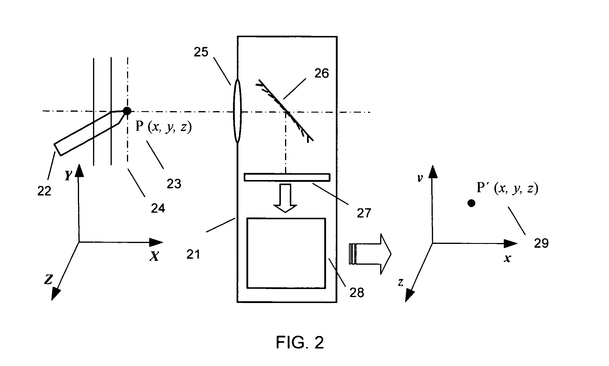
"The present invention provides a three-dimensional optical mouse system that can manipulate the pointer in three-dimensional space. The system uses a Micromirror Array Lens (MMAL) with fast response time and high optical efficiency. The MMAL can compensate for aberration and can be produced at a low cost. The system can be installed in a small-sized cellular phone and can extract information from the pointing tool without needing an electrical connection or ultrasound. The MMAL includes a plurality of micromirrors that act as a reflective focusing lens by making all light scattered from an object converge into a focal plane and meet periodic phase conditions among the micromirrors. The micromirrors are actuated by electrostatic force or electromagnetic force and can be controlled using a single image sensor. The MMAL can compensate for phase errors and can be produced at a low cost."

Problems solved by technology

This method is less perceivable and requires a great effort to learn and manipulate.
The time delays among the speakers determine the position of the pointing device.
This acoustic method can be susceptible to echoes, sound speed variation through different environmental conditions, and ultrasonic interference.
Interference between the magnetic fields and other materials around the system makes the exact positioning to be difficult.
Even the computer system itself generates a magnetic field and interferes with this kind of pointing device.
Currently available three-dimensional positioning devices discussed above or other methods require some specific environment and a large space due to the multiple transmitters and receivers.
These constraints are the major obstacles for the applications of three-dimensional pointing devices for most applications which need a pointing device.

Method used


Image

  • Three-dimensional optical mouse system
  • Three-dimensional optical mouse system
  • Three-dimensional optical mouse system

Examples


Embodiment Construction

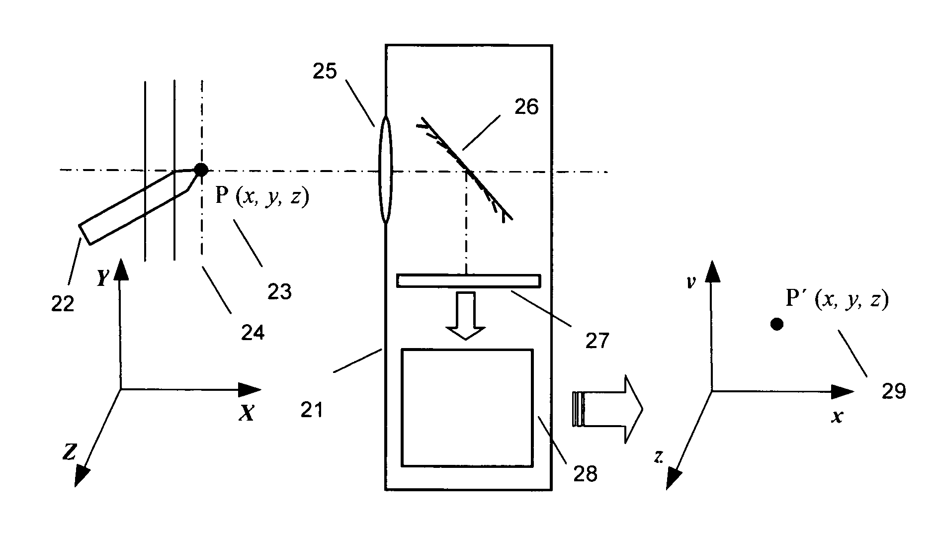
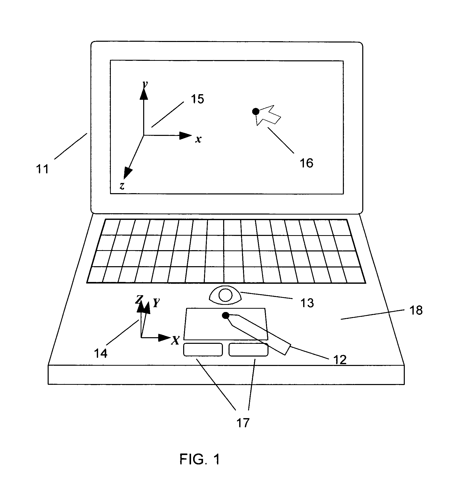
[0037]FIG. 1 shows a schematic diagram for the three-dimensional optical mouse system with a laptop computer 11. Pointing tool 12 can be moved freely in three-dimensional space to indicate the three-dimensional position in the viewing range of the image detecting device 13. This pointing tool 12 can be any object which can be imaged in the image sensor even user can use his / her finger as a pointing tool 12. Even wireless object can be a pointing tool 12. In the figure, pointing tool is appeared, but anything including finger of the user can be a pointing device for input. Three-dimensional optical mouse system 18 recognize the motions of the pointing tool in real space (X, Y, Z) 14. This point in real space coordinates 14 is converted into the new point 16 in computer operating coordinates 15 system. User can recognize the three-dimensional input by the three-dimensional optical mouse 18 better if the three-dimensional displaying device is used. With the special function keys 17, so...


PUM


Abstract

A three-dimensional optical mouse device with a Micromirror Array Lens (MMAL) is provided. To have the three-dimensional optical mouse system, a three-dimensional imaging device is used for detecting the motion of optical pointer or fingers of the user and gives a location of the pointer to computer working as a pointing device in three-dimension. This three-dimensional pointing system uses three-dimensional imaging device using MMAL with variable focal length.

Description

REFERENCE TO RELATED APPLICATIONS[0001]This application is a continuation-in-part of, and claims priority to U.S. patent application Ser. No. 10 / 822,414 filed Apr. 12, 2004, U.S. patent application Ser. No. 10 / 855,715 filed May 27 2004, U.S. patent application Ser. No. 10 / 857,714 filed May 28 2004, U.S. patent application Ser. No. 10 / 857,280 filed May 28, 2004, U.S. patent application Ser. No. 10 / 872,241 filed Jun. 18, 2004, U.S. patent application Ser. No. 10 / 893,039, filed Jul. 16, U.S. patent application Ser. No. 10 / 979,619 filed Nov. 2, 2004, U.S. patent application Ser. No. 10 / 983,353 filed Nov. 8, 2004, U.S. patent application Ser. No. 11 / 072,597 filed Mar. 4, 2005, U.S. patent application Ser. No. 11 / 072,296 filed Mar. 4, 2005, U.S. patent application Ser. No. 11 / 076,616 filed Mar. 10, 2005, U.S. patent application Ser. No. 11 / 191,886 filed Jul. 28, 2005 and U.S. patent application Ser. No. 11 / 294,944 filed Dec. 6, 2005, all of which are hereby incorporated by reference.BACKG...

Claims


Application Information

Patent Timeline
Patent Type & Authority Patents(United States)
IPC IPC(8): G09G5/08G06F3/033
CPCG06F3/0304
Inventor BAEK, SANG HYUNECHO, GYOUNG ILSEO, CHEONG SOO
Owner STEREO DISPLAY
Learn More