Sheath-mounted arterial plug delivery device

Inactive Publication Date: 2009-11-24
BOSTON SCI CORP +11
View PDF97 Cites 80 Cited by
  • Summary
  • Abstract
  • Description
  • Claims
  • Application Information

AI Technical Summary

Benefits of technology

[0007]The present invention provides an improved method and s

Problems solved by technology

An additional challenge of puncture closure devices comes when they are deployed many hours after access has b

Method used


Image

  • Sheath-mounted arterial plug delivery device
  • Sheath-mounted arterial plug delivery device
  • Sheath-mounted arterial plug delivery device

Examples


Example

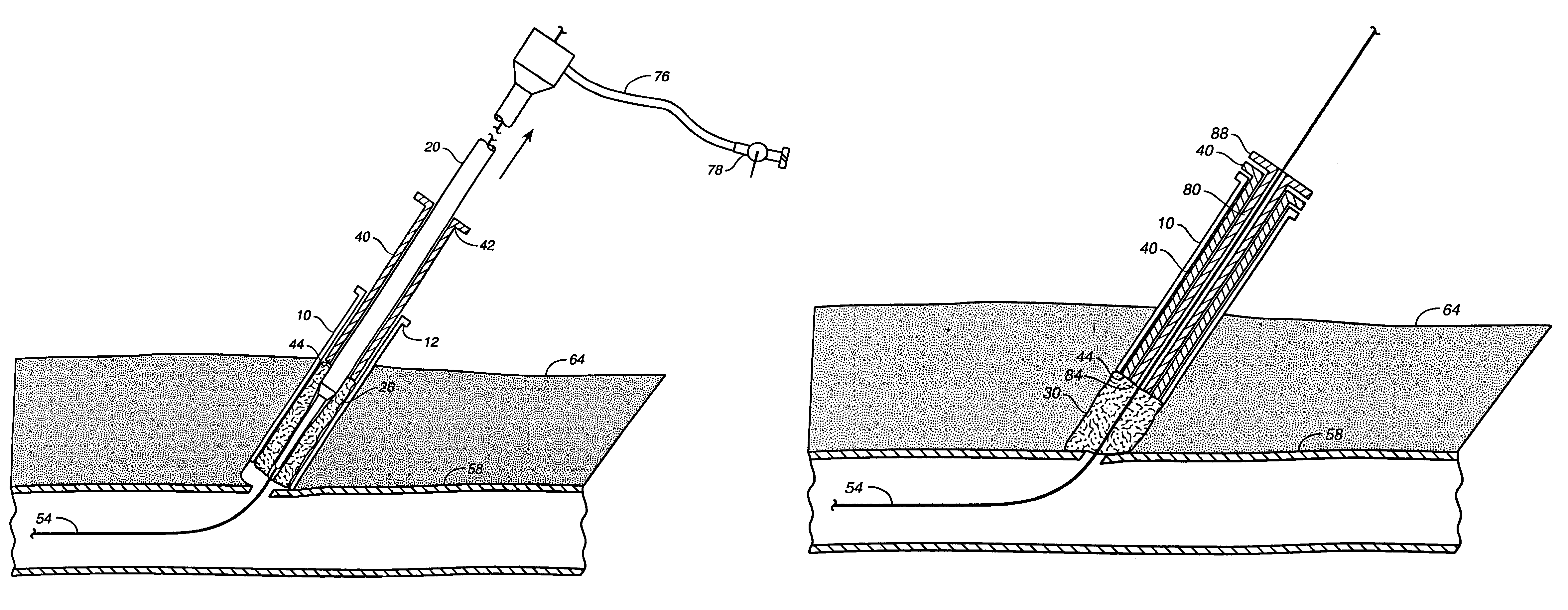
[0023]The present invention provides an access system that enables the user to access a blood vessel with a sheath that also incorporates a means for performing site closure. Upon completion of the interventional procedure, the closure device is deployed to close the puncture and the sheath is removed.

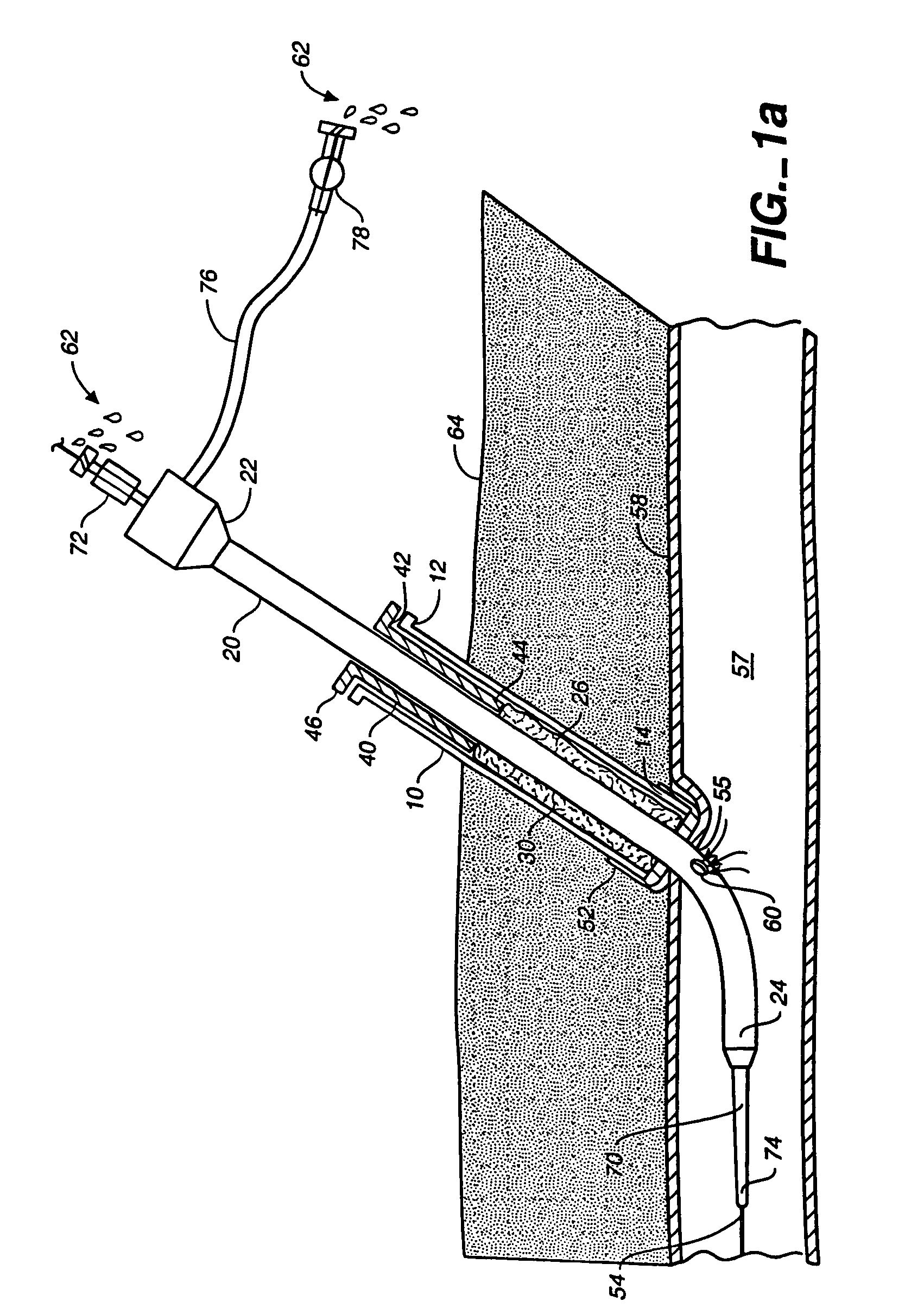
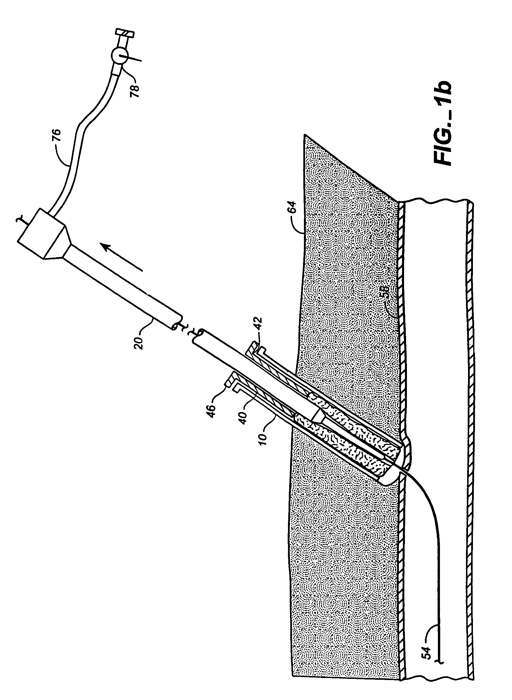
[0024]As shown in FIG. 1a, an access system for facilitating hemostasis of a blood vessel includes a delivery cannula 10 positioned coaxially around an access sheath 20, and a hemostatic promoting material 30 within the delivery cannula 10 for facilitating hemostasis of a blood vessel puncture when delivered adjacent to the puncture. In one preferred embodiment, the hemostatic material 30 is a hydrated and compressed sponge.

[0025]The delivery cannula 10 as shown in FIG. 1a is dimensioned such that its proximal end 12 can attach to the access sheath 20 at or near the access sheath proximal end 22, and such that the delivery cannula 10 distal end 14 terminates proximal to the distal end ...


PUM


Abstract

A method of facilitating hemostasis of a blood vessel puncture. The method includes the steps of inserting a tubular device into a puncture in a blood vessel to establish access to the blood vessel, providing a vessel closure system around the tubular device, introducing a hemostatic material into a space between the tubular device and vessel closure system, and delivering the hemostatic material adjacent to the puncture to facilitate hemostasis of the puncture.

Description

[0001]This application is a continuation of U.S. patent application Ser. No. 09 / 904,445, filed Jul. 11, 2001, now abandoned, which claims priority under 35 U.S.C. §119 to provisional U.S. patent application Ser. No. 60 / 218,431, filed Jul. 14, 2000. These applications are incorporated herein by reference in their entirety.FIELD OF THE INVENTION[0002]The present invention relates to a method and system for facilitating hemostasis of a blood vessel.BRIEF DESCRIPTION OF THE RELATED ART[0003]Numerous arterial puncture closure devices are known in the prior art. These include many mechanisms, such as plugs, sutures, intra-vascular structures and more. While these prior art devices vary in size and theory, they all require placement of distinct closure devices through a procedural sheath, sheath exchanges, or sheath removal prior to placement. By their very nature, these devices represent a separate procedure for access site closure after access site establishment / maintenance. The decision...

Claims


Application Information

Patent Timeline
IPC IPC(8): A61B17/03A61B17/00A61B19/00
CPCA61B17/0057A61B2019/462A61B2017/00654A61B2017/00637A61B2090/062
Inventor CRAGG, ANDREW H.ASHBY, MARK
Owner BOSTON SCI CORP
Why Eureka
Try Eureka