Controller for motor

a technology for controlling a motor and a control device, which is applied in the direction of motor control for motor oscillation damping, electric devices, driver interactions, etc., can solve the problems of low torque production, low torque production, and the motor disclosed in the patent document 1 cannot reduce the torque produced in the low torque and low torque operational state. reduce the torque, reduce the torque, and reduce the vibration of the vehicle

Inactive Publication Date: 2009-11-24
HONDA MOTOR CO LTD
View PDF6 Cites 14 Cited by
  • Summary
  • Abstract
  • Description
  • Claims
  • Application Information

AI Technical Summary

Benefits of technology

[0012]The present invention has been made in view of such circumstances, and it is an object of the present invention to provide a controller for a motor having two rotors that can reduce a change in torque produced by the motor when the motor operates at a low velocity with a low torque. It is another object of the present invention to provide a controller for a motor mounted on a vehicle as a propulsion force generating source that can reduce a change in torque produced by the motor when the vehicle is creeping, thereby reducing vibrations of the vehicle.

Problems solved by technology

Such a vehicle having the motor as the propulsion force generating source is likely to vibrate when the vehicle is creeping in situations, such as traffic congestion and slow speed driving, or immediately after start moving (when the vehicle runs on a low torque produced by the motor as an idling torque of the motor in a state where the accelerator of the vehicle is not manipulated).
However, ordinary permanent magnet type motor having a single rotor cannot change the strength of the field of the permanent magnet, and therefore, it is difficult to reduce a change in torque produced by the motor in the low-velocity and low-torque operational state.
Therefore, the motor disclosed in the Patent Document 1 cannot reduce a change in produced torque in the low-velocity and low-torque operational state.

Method used


Image

  • Controller for motor
  • Controller for motor
  • Controller for motor

Examples


Embodiment Construction

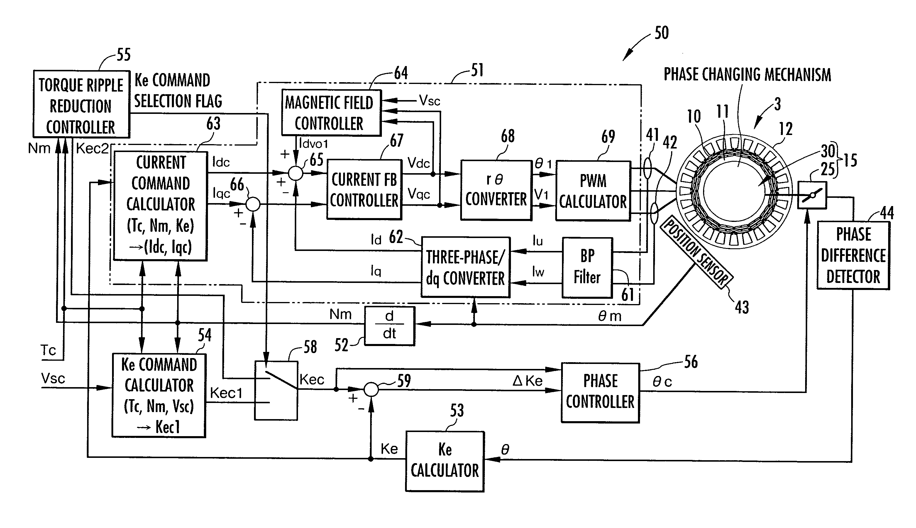
[0050]An embodiment of the present invention will be described with reference to FIGS. 1 to 10.

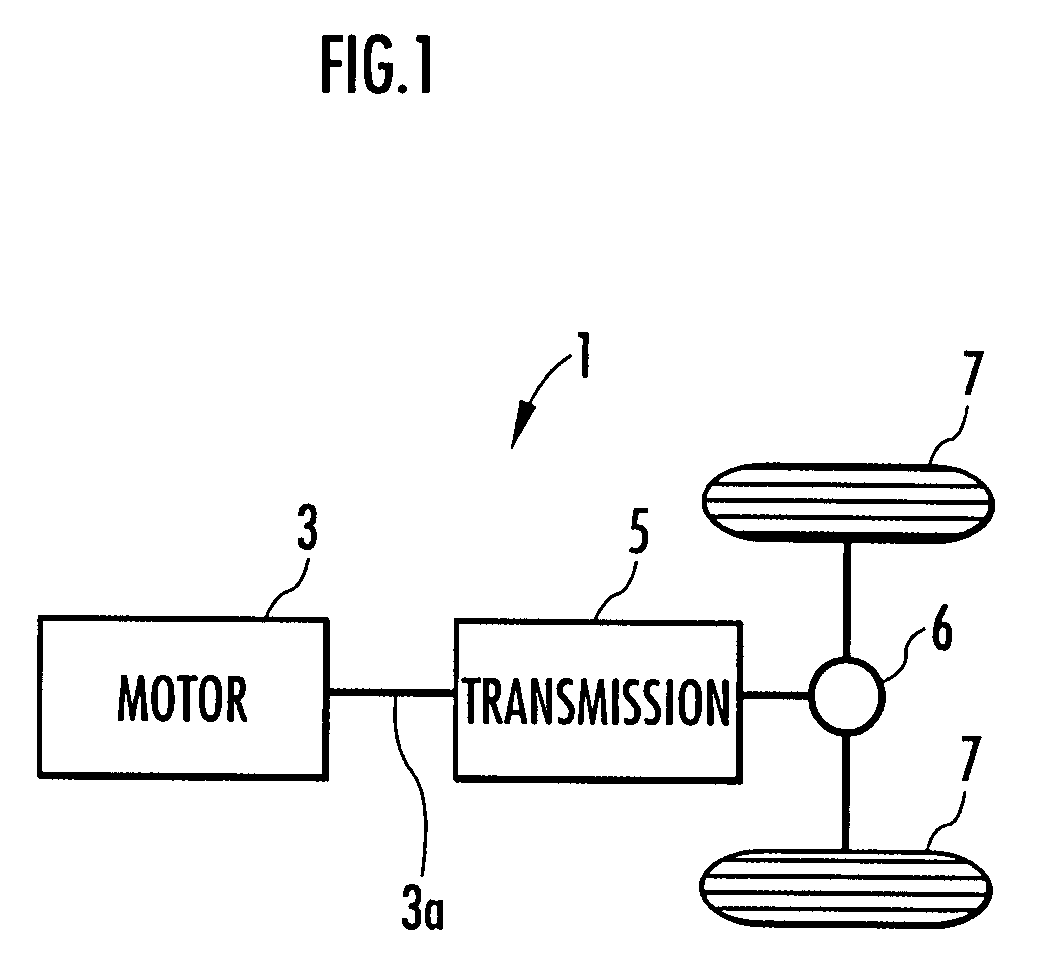
[0051]FIG. 1 is a schematic diagram showing a configuration of a vehicle on which a device according to this embodiment is mounted.

[0052]As shown in this drawing, a vehicle 1 is an electric-powered vehicle and has a motor 3 serving as a propulsion force generating source for the vehicle 1 and a transmission 5 for transmitting a torque produced by the motor 3 to drive wheels 7, 7 of the vehicle 1.

[0053]An output shaft 3a of the motor 3 is connected to an input end of the transmission 5. An output end of the transmission 5 is connected to the drive wheels 7, 7 of the vehicle 1 via a differential gear unit 6. Thus, the torque on the output shaft 3a of the motor 3 (a power running torque or a regenerative torque) is transmitted to the drive wheels 7, 7 via the transmission 5 and the differential gear unit 6.

[0054]The transmission 5 is constituted by an automatic gear box with a torque converte...


PUM


Abstract

A change in torque produced by a motor having two rotors is reduced when the motor operates in a low-velocity and low-torque operational state. The motor has a first rotor and a second rotor, each of which has a permanent magnet, and an output shaft capable of rotating integrally with the first rotor. The second rotor can relatively rotate with respect to the first rotor by a driving force from a phase difference changing driving device, and the phase difference between the rotors (rotor phase difference) can be changed by the relative rotation of the second rotor with respect to the first rotor. When the values of the torque and the rotational velocity of the motor lie within a predetermined region in the proximity of 0, the phase difference changing driving device adjusts the rotor phase difference to a predetermined phase difference for which the strength of a composite field of the permanent magnets is lower than a maximum strength.

Description

BACKGROUND OF THE INVENTION[0001]1. Field of the Invention[0002]The present invention relates to a controller for a motor that has two rotors each of which produces a field by a permanent magnet and can change the phase difference between the rotors.[0003]2. Description of the Related Art[0004]As a permanent magnet type motor, there has been known a double rotor type motor that has two rotors that are coaxially disposed and each have a permanent magnet for producing a field (for example, see Japanese Patent Application Publication No. 2002-204541 (referred to as Patent Document 1 hereinafter)). In the motor of this type, the two rotors can relatively rotate with respect to each other about the axis thereof, and the phase difference between the rotors can be changed by the relative rotation. By changing the phase difference between the rotors, the strength of a composite field (the magnitude of magnetic fluxes) of the fields produced by the permanent magnets of the rotors can be chan...

Claims


Application Information

Patent Timeline
Patent Type & Authority Patents(United States)
IPC IPC(8): H02P25/00B60L9/18H02K21/16H02P6/06H02P6/08H02P6/17H02P6/28H02P21/00H02P21/05H02P21/06H02P21/08H02P21/22H02P23/04H02P27/04H02P27/08
CPCB60L15/025H02K16/02H02K21/16H02P5/753H02P21/04B60L3/0061B60L7/12B60L11/1805B60L15/20B60L15/2009Y02T10/70H02P2207/03Y02T10/641Y02T10/643Y02T10/7077Y02T10/7258B60L2240/36B60L2240/421B60L2240/423B60L2240/427B60L2240/429B60L2250/26B60L2270/145B60L2220/16B60L50/52Y02T10/64Y02T10/72
Inventor ATARASHI, HIROFUMISATO, HIROMITSUFUKUCHI, MASANARIKAIZUKA, MASAAKI
Owner HONDA MOTOR CO LTD
Why Eureka
Try Eureka