
Pattern-based DC offset correction

a dc offset and pattern technology, applied in the field of pattern-based dc offset correction, can solve the problem that dc offset correction can be a relatively difficult problem to solve, and achieve the effect of reducing run length and reducing dc offs

Active Publication Date: 2009-11-24
MICROSEMI STORAGE SOLUTIONS
View PDF41 Cites 7 Cited by
  • Summary
  • Abstract
  • Description
  • Claims
  • Application Information

AI Technical Summary

Benefits of technology

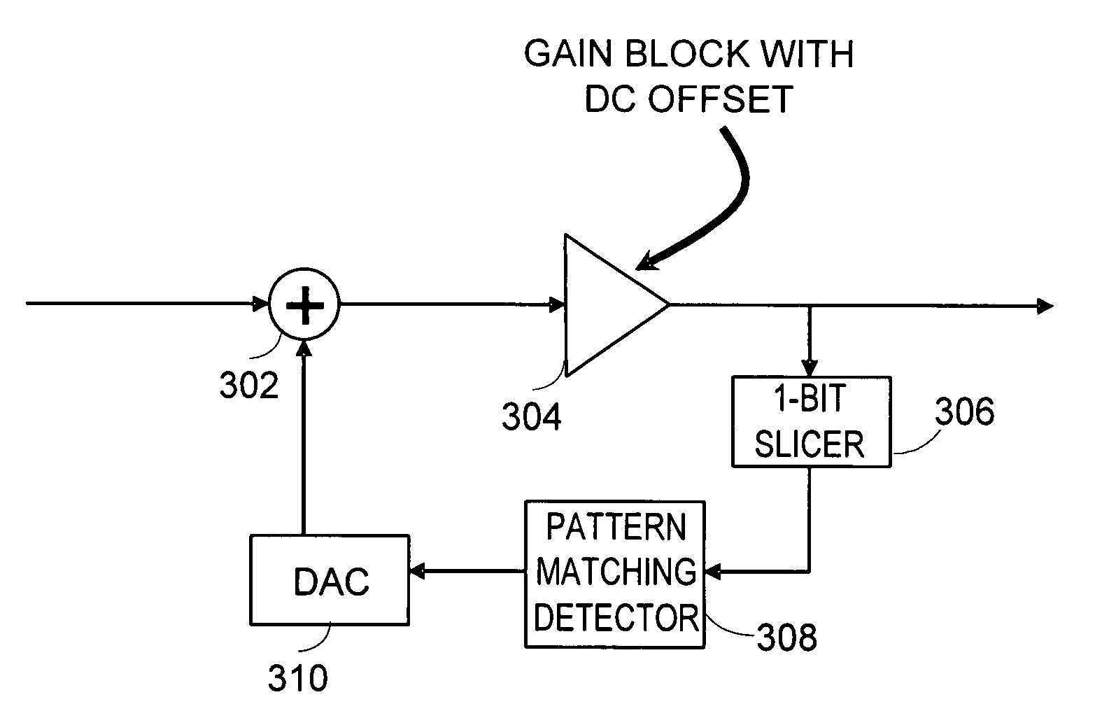
[0008]The invention can include, for example, a system configured to observe patterns in an output signal indicative of the presence of DC offsets. For example, an output of a gain stage can be sliced to +1s and −1s, and the presence of a DC offset can result in relatively long run lengths of either +1s or −1s. The relatively long run lengths are detected and corresponding corrections are made to reduce the run lengths, which typically reduces the DC offsets.

Problems solved by technology

DC offset correction can be a relatively difficult problem to solve.

Method used


Image

  • Pattern-based DC offset correction
  • Pattern-based DC offset correction
  • Pattern-based DC offset correction

Examples


Embodiment Construction

[0017]Although particular embodiments are described herein, other embodiments of the invention, including embodiments that do not provide all of the benefits and features set forth herein, will be apparent to those of ordinary skill in the art.

[0018]While described in the context of direct conversion radios, the principles and advantages described herein are applicable to any communication channel in which analog amplifiers with undesirable dc offsets may be present. This encompasses a very broad range of circuits inside and outside of data communications.

[0019]DC offset correction can be a relatively difficult problem to solve. Correction of DC offsets is desirable in many electronic environments, such as in direct conversion radios. Direct conversion radios and other analog signal processing circuits often use relatively high analog baseband gain. Signals processed by high-gain amplifiers typically do not contain useful content at DC. If spurious DC finds its way onto a signal, th...


PUM


Abstract

DC offsets in high-gain amplifiers should be corrected to avoid the signal distortion that would result from amplifier saturation. A predominantly digital technique is described in which a digital algorithm observes patterns in the sign of the amplifier output and drives a digital-to-analog converter (DAC), which reduces the amplifier's offset.

Description

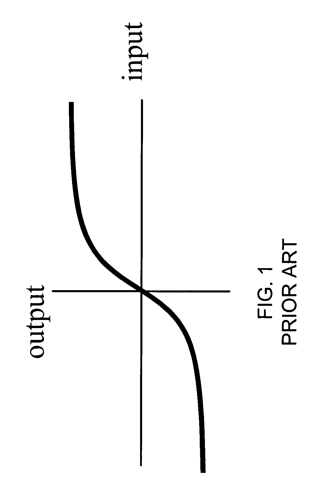
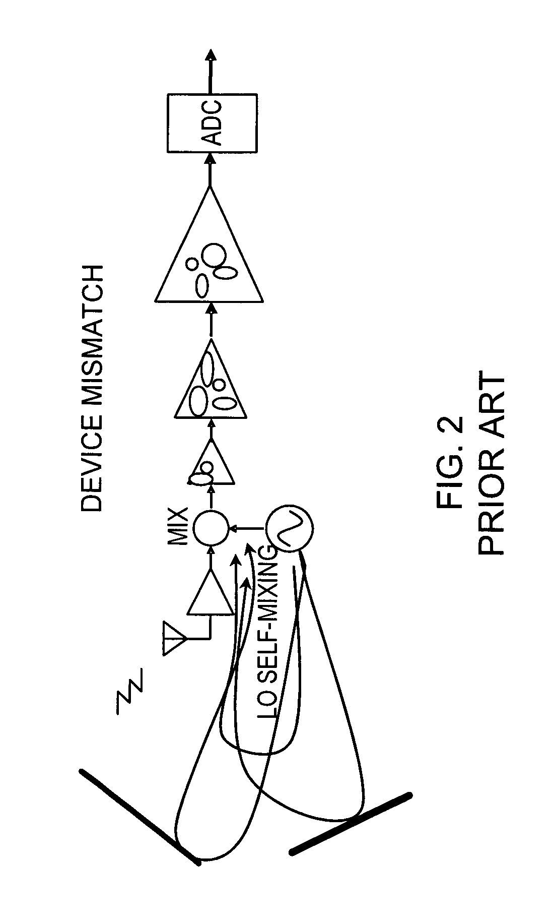
CROSS-REFERENCE TO RELATED APPLICATION[0001]This application claims the benefit under 35 U.S.C. § 119(e) of U.S. Provisional Application No. 60 / 886,576, filed Jan. 25, 2007, the entirety of which is hereby incorporated by reference.BACKGROUND[0002]1. Field of the Invention[0003]The invention generally relates to electronics. In particular, the invention relates to handling DC offsets in amplifiers.[0004]2. Description of the Related Art[0005]Typical analog amplifiers have a saturating input-output relationship, as illustrated in FIG. 1. Linear signal processing typically uses operation in the linear part of the curve—at smaller inputs levels. Large input signals, or high-gain can result in output saturation. If the ac portion of the desired input signal is sufficiently small, but the dc portion is relatively large, then with sufficient gain, the output will be saturated.[0006]In a direct conversion radio, a schematic of an example of which is illustrated in FIG. 2, there are several...

Claims


Application Information

Patent Timeline
Patent Type & Authority Patents(United States)
IPC IPC(8): H03F1/02
CPCH03F1/32H03F2200/375
Inventor ZORTEA, ANTHONY EUGENE
Owner MICROSEMI STORAGE SOLUTIONS
Learn More