
Tunable phase shifter and applications for same

a phase shifter and phase shifter technology, applied in the field of electromechanical devices, can solve the problems of serious coupling side effects in the mixer, wide use of direct conversion technology in wireless handsets, and special type of leakage, so as to reduce the dc offset

Inactive Publication Date: 2005-02-24
KYOCERA CORP
View PDF7 Cites 11 Cited by
  • Summary
  • Abstract
  • Description
  • Claims
  • Application Information

AI Technical Summary

Benefits of technology

It is desirable to provide a direct downconversion receiver that reduces DC offset in its demodulated baseband signal. It is therefore an object of the invention to provide a methodology for adaptively adjusting the receiver's characteristics in response to detected DC offset.
In accordance with one aspect of the invention, a tunable, low loss, phase shifting filter is provided. The filter may be configured as a low pass filter, a high pass filter or an all pass filter. The filter includes a variable dielectric constant ferro-electric component.
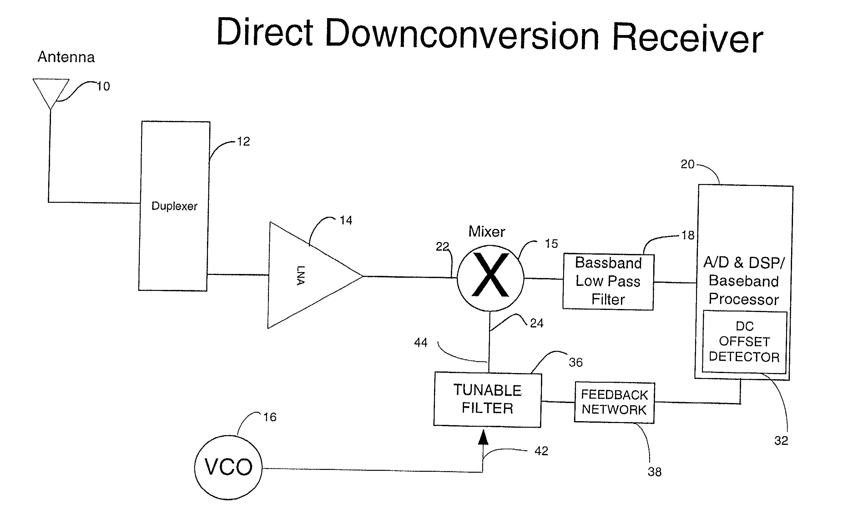
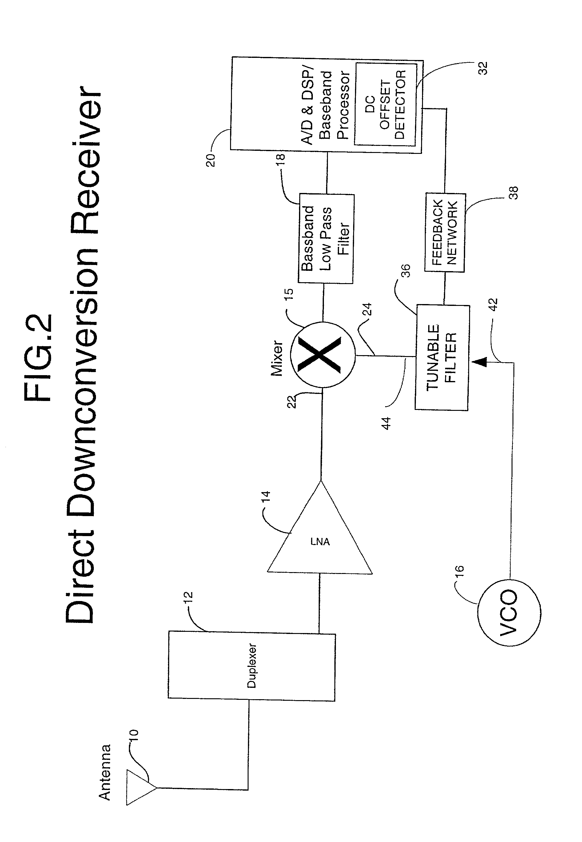
In accordance with another aspect of the invention, a direct downconversion receiver has a DC offset detector for detecting a DC offset in a received baseband signal and providing a negative feedback signal proportional to the detected DC offset. A tunable filter adjusts the phase of the receiver's local oscillator signal according to the negative feedback signal. A mixer mixes a received RF signal with the phase-shifted local oscillator signal to produce the baseband signal. Because of the negative feedback loop formed by the DC offset detector, tunable filter, and mixer, the amount of DC offset in the baseband signal is reduced.

Problems solved by technology

However, a number of problems have prevented the widespread use of direct conversion technology in wireless handsets.
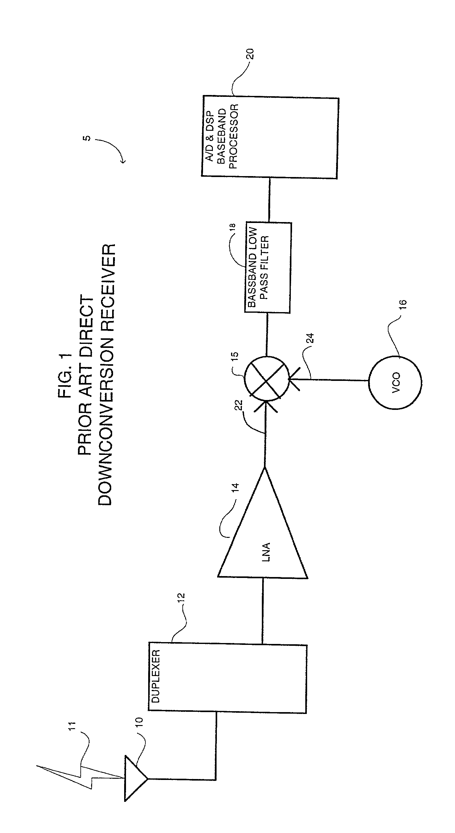
Thus, unlike a mixer in the IF stage of a superheterodyne receiver, serious coupling side effects can occur in the mixer 15.
These effects include non-linear effects of the mixer producing unwanted harmonics of the baseband signal.
This type of leakage is particularly problematic because the VCO output is typically many decibels higher in power than the output of the low noise amplifier 15.
Moreover, this type of leakage is exacerbated at the higher frequencies, such as the PCS band, used in wireless handsets.
Thus, LO leakage necessarily produces a DC offest.
These direct cancellation schemes suffer from the expensive hardware necessary and poor efficiency at cancelling the leakage component.

Method used


Image

  • Tunable phase shifter and applications for same
  • Tunable phase shifter and applications for same
  • Tunable phase shifter and applications for same

Examples


Embodiment Construction

Referring now to FIG. 2, a phase-compensated direct downconversion receiver 30 is illustrated. As discussed with respect to FIG. 1, downconversion receiver 30 may include antenna 10, duplexer 12, low noise amplifier 14, mixer 15, VCO 16, baseband low pass filter 18, and A / D & DSP baseband processor 20. In addition, baseband processor 20 includes a DC offset detector 32. Although shown integrated with baseband processor 20, DC offset detector 32 may be distinct from baseband processor 20. It will be appreciated that DC offset detector 32 may be implemented in hardware or software or a combination of the two in a number of ways.

Regardless of the implementation, DC offset detector 32 functions to provide a measure of the amount of DC offset present in the demodulated baseband signal recovered by baseband processor 20. For example, DC offset detector 32 could average or low pass filter the waveform produced by the analog-to-digital converter (A / D) within baseband processor 20. DC off...


PUM


Abstract

The present invention provides a phase shifting filter and a phase compensating direct downconversion receiver. A DC offset detector detects a DC offset in a received baseband signal and provides a feedback signal. A tunable filter phase shifts a local oscillator signal responsive to the feedback signal. The phase-shifted local oscillator signal is used to directly downconvert a received RF signal, whereby DC offset in the resulting baseband signal is reduced.

Description

BACKGROUND 1. Field of the Invention The field of the present invention is electronics. More particularly, the present invention relates to direct conversion receivers in wireless communication devices. 2. Description of Related Art Most present wireless communication devices use transceivers (transmitters and receivers) that have an intermediate frequency (IF) stage between the baseband and the radio frequency (RF) stages. Transceivers with an IF stage are called superheterodyne transceivers. The compelling commercial drive for cheaper, more reliable, longer lasting and smaller wireless communication devices is causing many in the industry to attempt to eliminate the IF stage. This would produce a saving in number of components, cost and size. Transceivers without IF stages are called direct down conversion transceivers, since the RF signal is converted directly to a baseband signal from the RF signal. They are also known as zero IF transceivers. Since a superheterodyne recei...

Claims


Application Information

Patent Timeline
Patent Type & Authority Applications(United States)
IPC IPC(8): H01P1/203H03H7/01H03H7/12H03H7/20H04B1/30
CPCH03H7/0123H03H7/0153H04B1/30H03H7/20
Inventor TONCICH, STANLEY S.WALLACE, RAYMOND CURTIS
Owner KYOCERA CORP
Learn More