Catheter with flexible pre-shaped tip section

a tip section and flexible technology, applied in the field of catheters, can solve the problems of difficult control of the distal end of the straight catheter for effective ablation about the circumference, less effective procedures, and inability to stabilize or support the catheter, so as to improve the ability of the tip assembly to contact, improve the ability of ablation and mapping, and improve the safety features

Active Publication Date: 2009-11-24
BIOSENSE WEBSTER INC
View PDF32 Cites 102 Cited by
  • Summary
  • Abstract
  • Description
  • Claims
  • Application Information

AI Technical Summary

Benefits of technology

[0004]The present invention is directed to a catheter configured for mapping and ablation at a junction of a generally flat open region of the heart such as the left atrium and a generally cavernous region of the heart, such as a pulmonary vein or an antrum of several (more than one) pulmonary veins, referred to as a pulmonary venous antrum. In one embodiment, the catheter has an intermediate section with a pre-shaped section at its distal end, and a tip assembly adapted for mapping and / or ablation that is attached distally to the pre-shaped section by a flexible section that allows the tip assembly to be moved generally independently of the intermediate section. In one embodiment, the catheter comprises an elongated flexible tubular catheter body having proximal and distal ends. The deflectable intermediate section is mounted on the distal end of the tubular body and comprises at its distal end the pre-shaped curve whose curvature is generally opposite of the direction of deflection and generally conforms to a pulmonary vein or pulmonary venous antrum. The tip assembly which can have a generally straight configuration is attached to the end of the pre-shaped curve of the intermediate section by the flexible section which is configured with preset angles to extend the tip assembly off-axis and / or off-plane relative to the pre-shaped curve of the intermediate section. The intermediate section of the catheter is adapted to rest within the generally cavernous structure providing stability to the tip assembly. The flexible section improves the ability of the tip assembly to contact and remain in contact with surrounding tissues of variable contour without undue pressure. Moreover, the flexible tubing may be reinforced to provide the tip assembly with lateral stability. Accordingly, the catheter of the present invention has improved safety features and improved ablation and mapping capabilities.
[0005]In one embodiment, the tip assembly is configured as an ablation assembly that may be irrigated, comprising a plurality of irrigation ports in between which an ablation coil electrode is wound. A porous covering, preferably made of expanded polytetrafluoroethylene, covers the coil electrode and irrigation ports. Fluid passes through the irrigation ports to the porous covering, which then disperses the fluid around the ablation assembly. This irrigation generally enables the creation of deeper lesions.
[0006]In use, the distal end of the catheter is inserted into the heart of a patient. The pre-shaped section is deflected or otherwise positioned to sit in the generally cavernous region of the heart. The off-axis angle of the tip assembly readily allows the tip assembly to contact the surrounding tissue despite varied surface contour. As the user operates the catheter and maneuvers the tip assembly, the pre-shaped section advantageously maintains the tip assembly just outside the ostium of the cavernous region while the flexible section advantageously allows the tip assembly to flex from the preset off-axis angle as needed in order to remain in contact with the tissue. In one embodiment, as the tip assembly encounters protrusions and recesses outside the ostium of the pulmonary vein or pulmonary venous antrum, the tip assembly is jarred from its preset off axis angle but the flexible section allows the tip assembly to conform and ride along on the uneven surface without displacing the pre-shaped curve.

Problems solved by technology

However, at the intersection of a generally cavernous or tubular region and a generally flat region in or around the heart, this procedure can be less effective.
For example, when the line of block to be ablated is about the circumference of the cavernous or tubular region, the catheter is not stabilized or supported except at the tip where it contacts the heart making it is difficult to manipulate and control the distal end of a straight catheter for an effective ablation about the circumference.
However, due to the shape and material of the balloon, the balloon often becomes dislodged, thereby adversely affecting the accuracy of the lesion created outside the ostium of the pulmonary vein or pulmonary venous antrum.
Moreover, due to the shape of regions near the pulmonary vein and / or the antrum of pulmonary veins, where a generally flat structure joins a generally cavernous structure, it is difficult to maintain a catheter in stable position.
In a catheter that approaches the intersection of the ostium and the atrium in a “forward” direction, the disparity between the generally motionless (or out of synch) catheter and the heart makes it difficult to maintain stable contact between the catheter tip and the intersection of the flat and cavernous regions in a beating moving heart.
An unsupported and thus unsynchronized catheter used in these regions may be inadvertently advanced into the pulmonary vein or venous antrum.
Also, the nonuniform contours at the intersection of the pulmonary vein or venous antrum and surrounding tissue can make it difficult to contact recessed areas without excess pressure on the protruding areas increasing the risk of perforation.

Method used


Image

  • Catheter with flexible pre-shaped tip section
  • Catheter with flexible pre-shaped tip section
  • Catheter with flexible pre-shaped tip section

Examples


Embodiment Construction

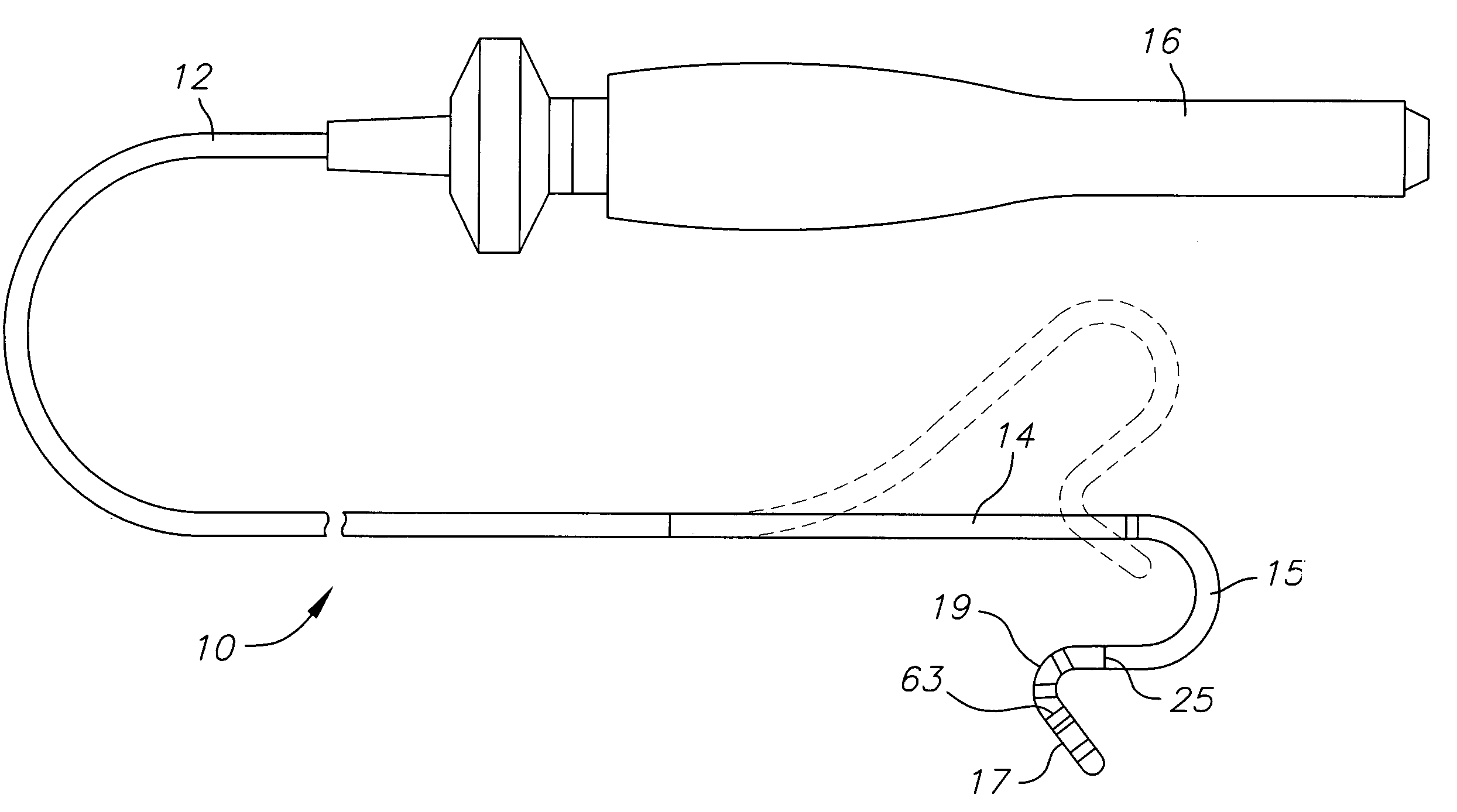
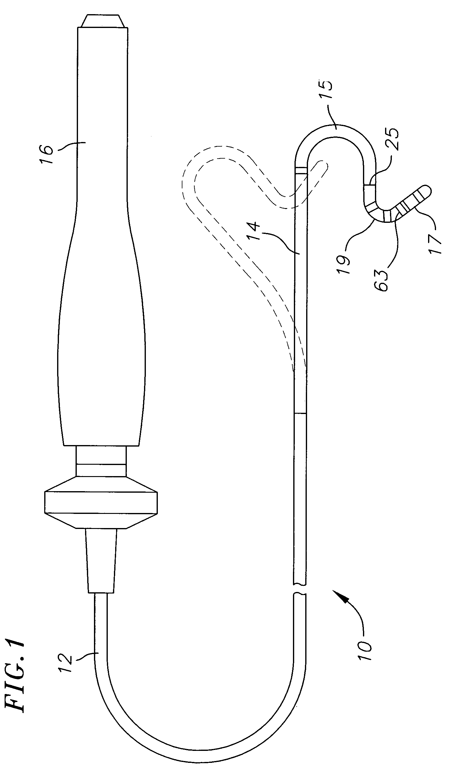
[0026]Referring to FIG. 1, the present invention provides a catheter 10 having a tip assembly 17 at its distal end. The catheter comprises an elongated catheter body 12 having proximal and distal ends, a deflectable intermediate section 14 at the distal end of the catheter body 12, and a control handle 16 at the proximal end of the catheter body. In accordance with a feature of the present invention, the tip assembly 17 extends distally from a preformed section 15 at the distal end of the intermediate section 14 and is connected thereto by a flexible section 19. In the illustrated embodiment, the tip assembly 17 is adapted for ablation although it is understood by one of ordinary skill in the art that the tip assembly may be adapted for mapping applications, as well.

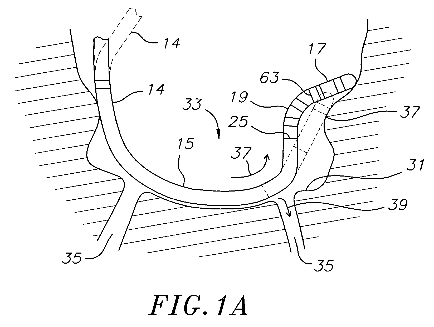
[0027]In the embodiment of FIG. 1A, the preformed section 15 is a curve which enables the catheter distal end when advanced and maneuvered in a generally cavernous region or structure such as a PV ostium 31 or antrum 33 ...


PUM


Abstract

A catheter for mapping and / or ablating continuous linear or circumferential lesions at the intersection of a generally flat structure, such as the left atrium, and the ostium of generally cavernous regions of the heart, including pulmonary vein and the pulmonary venous antrum, comprises a catheter body with an intermediate section that is connected to a tip assembly by a highly flexible section. The intermediate section has at its distal end a preformed section, e.g., a curve, the intermediate section being deflectable in a direction opposite to the curve. The highly flexible section presets the tip assembly at an off-axis and / or off-plane angles from the preformed section. Accordingly, the preformed section is adapted to sit in the region and the preset angles of the ablation assembly enable contact with surrounding tissue. A high bending modulus enables the flexible section absorb displacement force applied to the ablation assembly, such as when the tip assembly encounters uneven tissue surface, without displacing the curve from the region. The tip assembly can be irrigated as enabled by a plurality of irrigation ports, a coil electrode, and a porous covering to disperse fluid over the outer surface of the tip assembly.

Description

FIELD OF THE INVENTION[0001]The invention is directed to a catheter having a tip assembly for mapping and / or ablating regions of or near a heart, including an intersection between a generally flat region such as the body of the left atrium and a generally cavernous regions such as a pulmonary vein or the antrum of two or more pulmonary veins, the intersection being referred to as the ostium or opening of the generally cavernous region.BACKGROUND OF THE INVENTION[0002]Atrial fibrillation is a common sustained cardiac arrhythmia and a major cause of stroke. This condition is initiated by wavelets originating at or near the intersection of a generally cavernous region such as a pulmonary venous atrium or a pulmonary vein and a generally flat structure such as the left atrium. The condition is perpetuated by reentrant wavelets propagating in an abnormal atrial-tissue substrate. Various approaches have been developed to interrupt wavelets, including surgical or catheter-mediated atriotom...

Claims


Application Information

Patent Timeline
Patent Type & Authority Patents(United States)
IPC IPC(8): A61B5/04A61B18/14
CPCA61B18/1492A61M25/003A61M25/0068A61M25/008A61M25/0082A61M25/0147A61B2017/00867A61B2018/00375A61B2018/1435C08L2201/12A61M25/0071A61M2025/004A61M2025/0161A61M25/007
Inventor WORLEY, SETH J.SHARAREH, SHIVA
Owner BIOSENSE WEBSTER INC
Why Eureka
Try Eureka