Roof frame for a motor vehicle

a technology for motor vehicles and sunroofs, which is applied in the direction of roofs, other domestic objects, transportation and packaging, etc., can solve the problems of high requirements for the stiffness of the frame itself, which cannot be met with a frame of thermoplastic, and the cost of making it corrosion resistant, etc., to achieve high intrinsic stiffness, low cost, and low weight

Active Publication Date: 2009-12-01
LANXESS PERFORMANCE MATERIALS GMBH +1
View PDF6 Cites 10 Cited by
  • Summary
  • Abstract
  • Description
  • Claims
  • Application Information

AI Technical Summary

Benefits of technology

[0009]The task that is the basis of the invention is to produce a frame of the kind mentioned initially, that is characterized by low weight, high intrinsic stiffness and the capability of being manufactured at low cost.
[0012]In particular, the inserted piece can be made of metal and be a thin -walled sheet. In this case the inserted piece in particular is a deep-drawn piece, so that when the invention-specific frame is manufactured, not only the specific properties of the materials used, but also the two processing procedures, metal deep drawing and injection molding, add to the cost-effectiveness. Thus the result is a component formed by the frame base element with reliable, reproducible and tight manufacturing tolerances. It is especially manufactured so that a thin-walled, deep-drawn, stamped and still intrinsically unstable sheet piece or profile is inserted into the appropriate injection-molding tool, and the plastic structure with a suitable material, i.e., with a thermoplastic or a duroplastic, is sprayed onto the sheet piece according to one of the injection-molding procedures carried out in the usual way, which reinforces the sheet piece and thus the entire structure. By spraying the plastic structure onto the inserted piece serving as a reinforcing element, thus the thin-walled sheet structure of the inserted piece can be effectively stabilized.
[0019]The ribbed structure that engages into the profiling of the particular inserted piece, especially is a crisscrossed or zigzag ribbed structure. Such a structure is especially effective at countering the tendency of the inserted piece to buckle. But fundamentally any ribbed pattern is possible.
[0021]Additionally, it is advantageous if the at least one inserted piece has holes on its base, each of which serving as an anchoring point for the plastic of the frame base element. Then with the injection-molding process, the material placed in the affected injection-molding tool penetrates through the holes of the inserted piece in question, thus causing the inserted piece to be anchored on the plastic.
[0023]In addition, a crash console can be attached on the inserted piece placed in the area of the frame base element's side stringer, which [console] is attached in the area of a B pillar with the vehicle chassis in question. Such a crash console can increase the stiffness and stability of the vehicle body shell in the area of the B pillar in question.
[0025]To increase the seal integrity of the frame, and improve adhesion of the plastic used to produce the frame base element on the inserted piece, the inserted piece can have a plastic coating. The plastic coating also forms a corrosion protection for an inserted piece made of metal, especially in the area of its edges.

Problems solved by technology

Especially with a frame mounted on the vehicle chassis, great demands are made for the stiffness of the frame itself, which possibly cannot be met with a frame of thermoplastic.
Such a frame, which due to material, is of heavier weight and due to fabrication, offers limited shaping options, is as a rule provided with further structural sheet elements.
Also, the options for functional integration are limited.
Additionally, it is expensive to make it corrosion resistant.
With such a modular design of the sliding sunroof frame, expensive sealing measures must be taken in the transitional areas between the front frame piece produced from plastic and the frame side stringers embodied as extruded aluminum profiles.

Method used


Image

  • Roof frame for a motor vehicle
  • Roof frame for a motor vehicle
  • Roof frame for a motor vehicle

Examples


Embodiment Construction

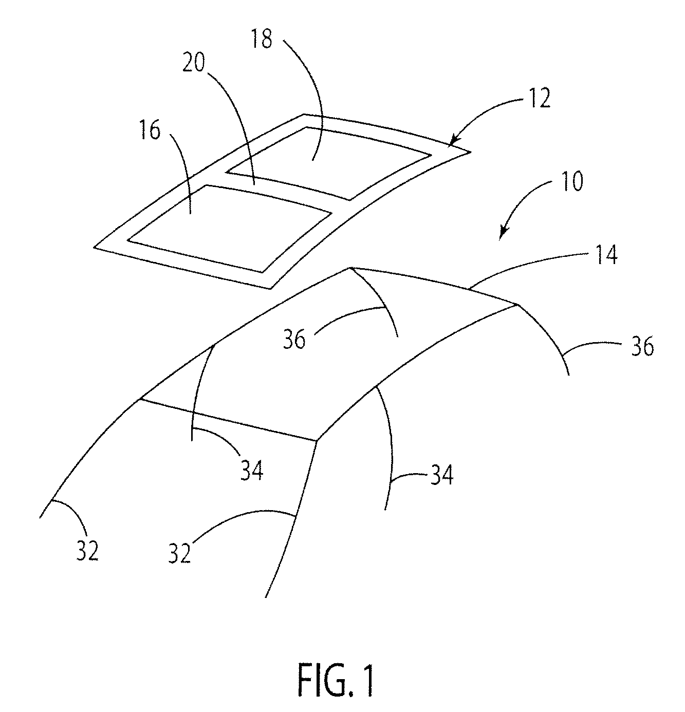
[0034]FIG. 1 depicts a motor vehicle 10 that is equipped with a vehicle roof embodied as a panorama roof. For this, the vehicle roof has a roof frame 12, that is embodied as a frame from above on a chassis frame 14, thus as a so-called top-load frame, and represents a sliding sunroof of motor vehicle 10.

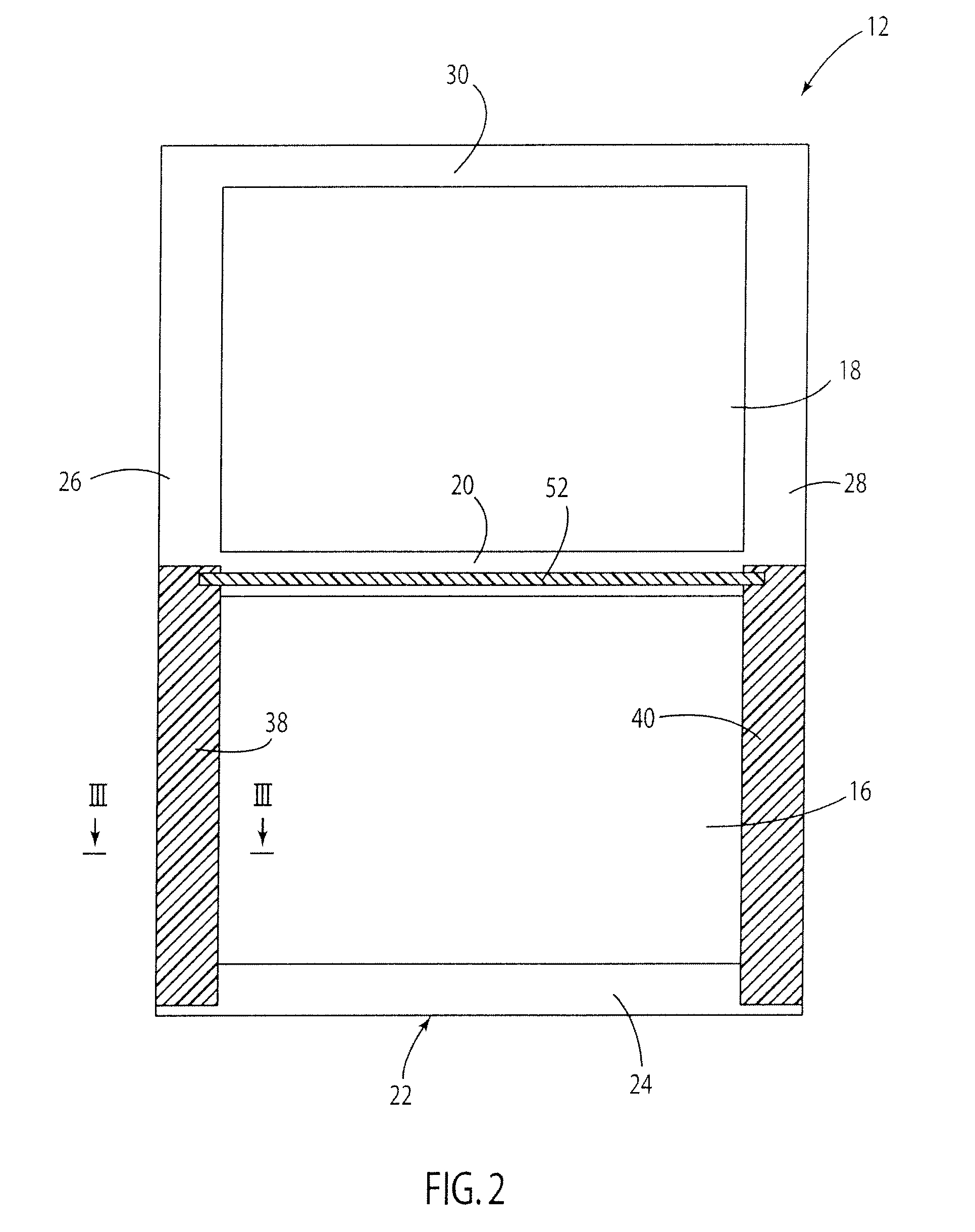
[0035]To form a panorama roof that extends in the vehicle's longitudinal direction over the entire passenger compartment of motor vehicle 10, the roof frame has a front roof aperture 16 and a rear roof aperture 18. The front roof aperture 16 and the rear roof aperture 18 are separated from each other by a transverse truss 20. If desired, front roof aperture 16 can be closed by a cover element, not shown in greater detail, or at least partially released. The rear roof aperture 18 is covered by a rigidly mounted transparent glass or polycarbonate pane element. The two roof apertures 16 and 18 can be darkened by a rollup screen not shown here in greater detail.

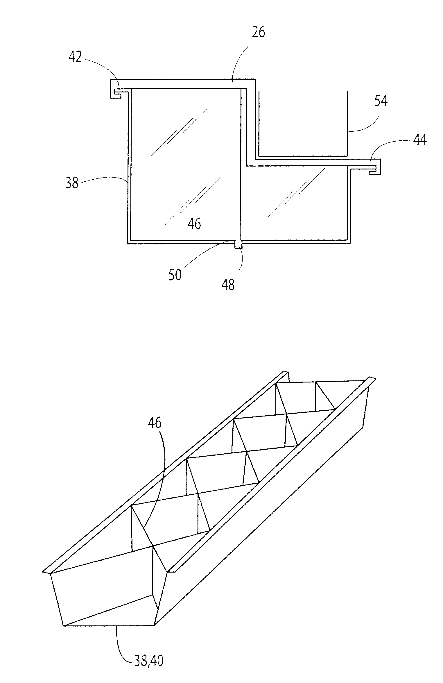
[0036]The frame 12 depicte...


PUM

PropertyMeasurementUnit
plasticaaaaaaaaaa
structureaaaaaaaaaa
areaaaaaaaaaaa

Abstract

A frame for a vehicle sliding sunroof or tilt-slide sunroof is proposed, comprising at least one single-piece frame base element (22), that is embodied as a plastic injection-molded piece and comprises at least one front frame piece (24) and two side stringers (26, 28) that are directed in the vehicle's longitudinal direction. For formation of a light and stiff frame, the frame base element (22) according to the invention is embodied as a composite component, and provided with at least one profile- or cup-shaped inserted piece (38, 40) that serves as a reinforcing element.

Description

CROSS REFERENCE TO RELATED APPLICATIONS[0001]This invention relates to, and claims the benefit of priority from DE Application No. 10 2006 046 122.3, filed Sep. 28, 2006.BACKGROUND OF THE INVENTION[0002]1. Field of the Invention[0003]The invention relates to a frame for a sliding vehicle sunroof or a tilt-slide sunroof with the features of the preamble of patent claim 1.[0004]2. Related Art[0005]One such frame is known, for example, from DE 203 17 140 U1, and formed from a plastic injection-molded piece, that thus is produced from a thermoplastic and that has one front frame part and two side stringers that have one-piece configurations. Guide rails are integrated onto the side stringers, onto which for optional closing or at least partial release of a roof opening, a cover element of the affected sliding sunroof or tilt-slide sunroof is guided. For operation of the cover element, a drive motor can be placed in the area of the front frame piece. Owing to design as a plastic injectio...

Claims


Application Information

Patent Timeline
Patent Type & Authority Patents(United States)
IPC IPC(8): B60J7/00
CPCB29C45/14631B29C45/14778B29C70/74B62D29/004B60J7/022B62D29/001B29C45/14311B29C2045/14327B29L2031/30B29L2031/3002B29K2705/02B29C2045/14442
Inventor POLLAK, MARTINRAINER, MATHIASKOCH, BORIS
Owner LANXESS PERFORMANCE MATERIALS GMBH
Why Eureka
Try Eureka