Turbine cascade structure

a turbine blade and cascade technology, applied in the direction of marine propulsion, vessel construction, other chemical processes, etc., can solve the problems of reducing the efficiency of the blade cascade, and difficult to control the incident angle of the working fluid, so as to reduce the secondary flow loss

Active Publication Date: 2009-12-01
KK TOSHIBA
View PDF26 Cites 38 Cited by
  • Summary
  • Abstract
  • Description
  • Claims
  • Application Information

AI Technical Summary

Benefits of technology

[0022]The present invention has been conceived in consideration of the above circumstances, and an object of the present invention is to provide a turbine blade cascade structure capable of reducing a secondary flow loss due to secondary flow even if a flow rate of working fluid caries and incident angle of the working fluid to a front edge of a blade varies accordingly.
[0034]In the turbine blade cascade structure according to the present invention, a corner portion defined by the blade body and the wall surface is provided with a coating having a cross section formed as a protruded portion to form a curved surface. The base portion of the protruded portion is extended to the upstream side to increase the surface area. The flow rate of the working fluid flowing to the curved protruded portion with an enlarged surface area is accelerated to suppress generation of the horseshoe vortex from the front edge of the blade body.
[0035]The blade cascade structure of the present invention may be applied to the rotor blade of the turbine and stationary blade (turbine nozzle), and allowed to further reduce the secondary flow loss by diminishing the strength of the passage vortex through the flow of the working fluid.

Problems solved by technology

The secondary flow loss of the secondary flow may cause great loss as serious as the profile loss defined by the configuration of the blade type.
The secondary flow vortex disturbs the main flow (drive fluid) as the cause of the reduction in the blade cascade efficiency.
As the flow rate of the working fluid flowing into the blade bodies 1a and 1b may vary with the load (output), it is difficult to control an incident angle of the working fluid especially at a time of the start-up operation, the partial load operation, and the like.

Method used


Image

  • Turbine cascade structure
  • Turbine cascade structure
  • Turbine cascade structure

Examples


first embodiment

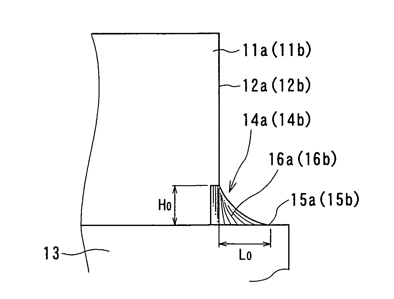
[0066]FIG. 1 is a conceptual view of a turbine blade cascade structure according to the present invention as an example of a turbine rotor blade.

[0067]In the turbine blade cascade structure according to the present invention, a plurality of rotor blades are arranged in series to be provided on a substantially flat wall surface 13 like a turbine disc. In the structure, corner (root) portions defined by the wall surface 13 and front edges 12a and 12b of adjacent blade bodies 11a and 11b circumferentially arranged in series are provided with coatings (fillets) 14a and 14b which extend toward the upstream of the working fluid from the front edges 12a and 12b, respectively.

[0068]The coatings (fillets) 14a and 14b are provided to cover the corner portions of the front edges 12a and 12b of the blade bodies 11a and 11b, respectively.

[0069]Referring to FIG. 2, the coatings 14a and 14b have cross sections formed as protruded portions 16a and 16b raised from extended end portions 15a and 15b u...

second embodiment

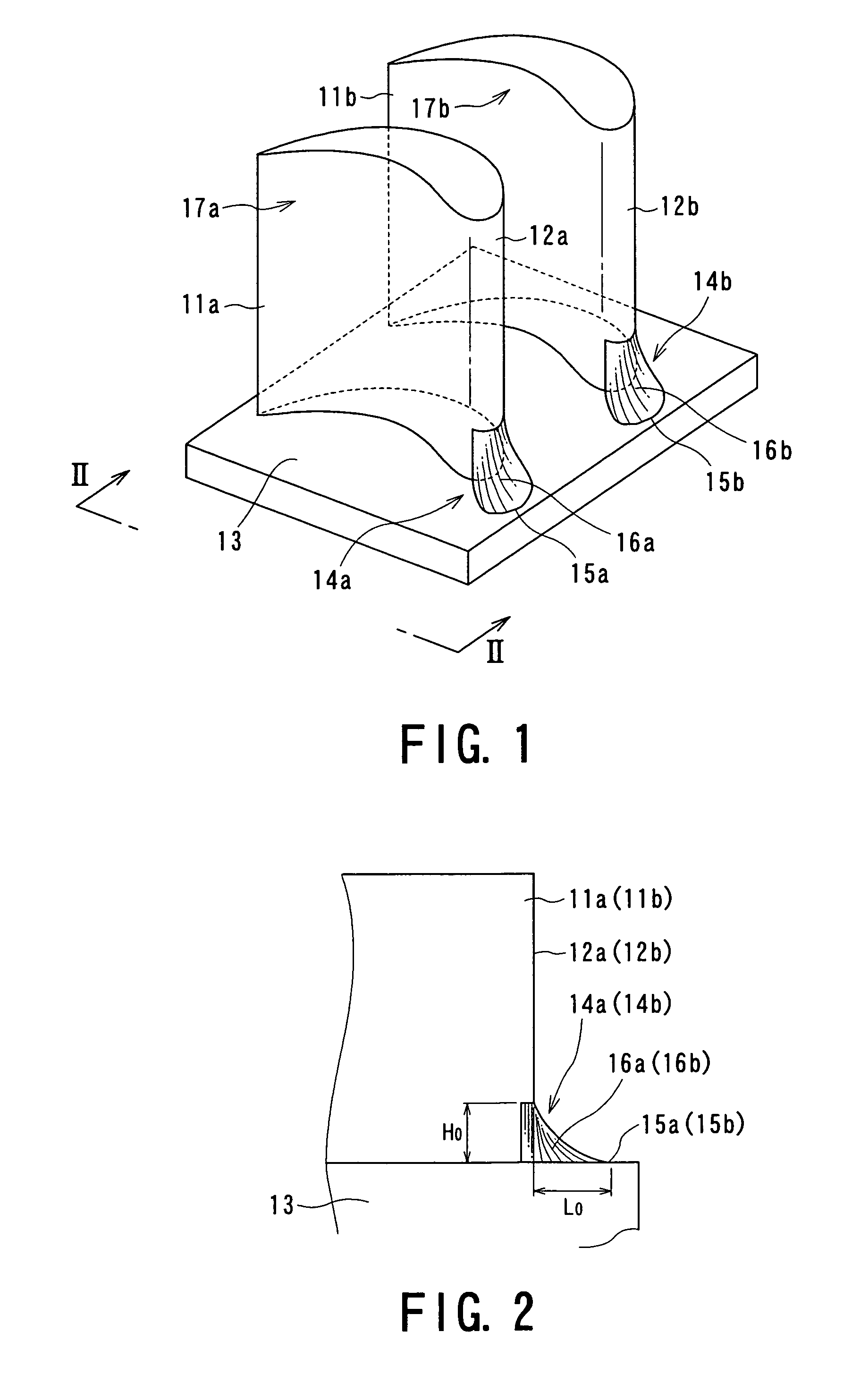
[0072]FIGS. 3 and 4 are conceptual views of a turbine blade cascade structure according to the present invention as an example of a turbine rotor blade.

[0073]Elements which are the same as those constituting the first embodiment will be designated with the same reference numerals.

[0074]Likewise the first embodiment, in the turbine blade cascade structure according to the embodiment, the corner portion defined by the wall surface 13 like a turbine disc having a substantially flat surface, and the front edges 12a and 12b of the adjacent blade bodies 11a and 11b arranged in series circumferentially on the wall surface is provided with coatings (fillets) 14a and 14b which extend therefrom toward the upstream side of the working fluid. The coatings 14a and 14b have fan-like configurations extending from the front edges 12a and 12b toward the front sides 17a and 17b, and the back sides 18a and 18b of the blade bodies 11a and 11b, respectively.

[0075]Assuming that each angle of a sector the...

fourth embodiment

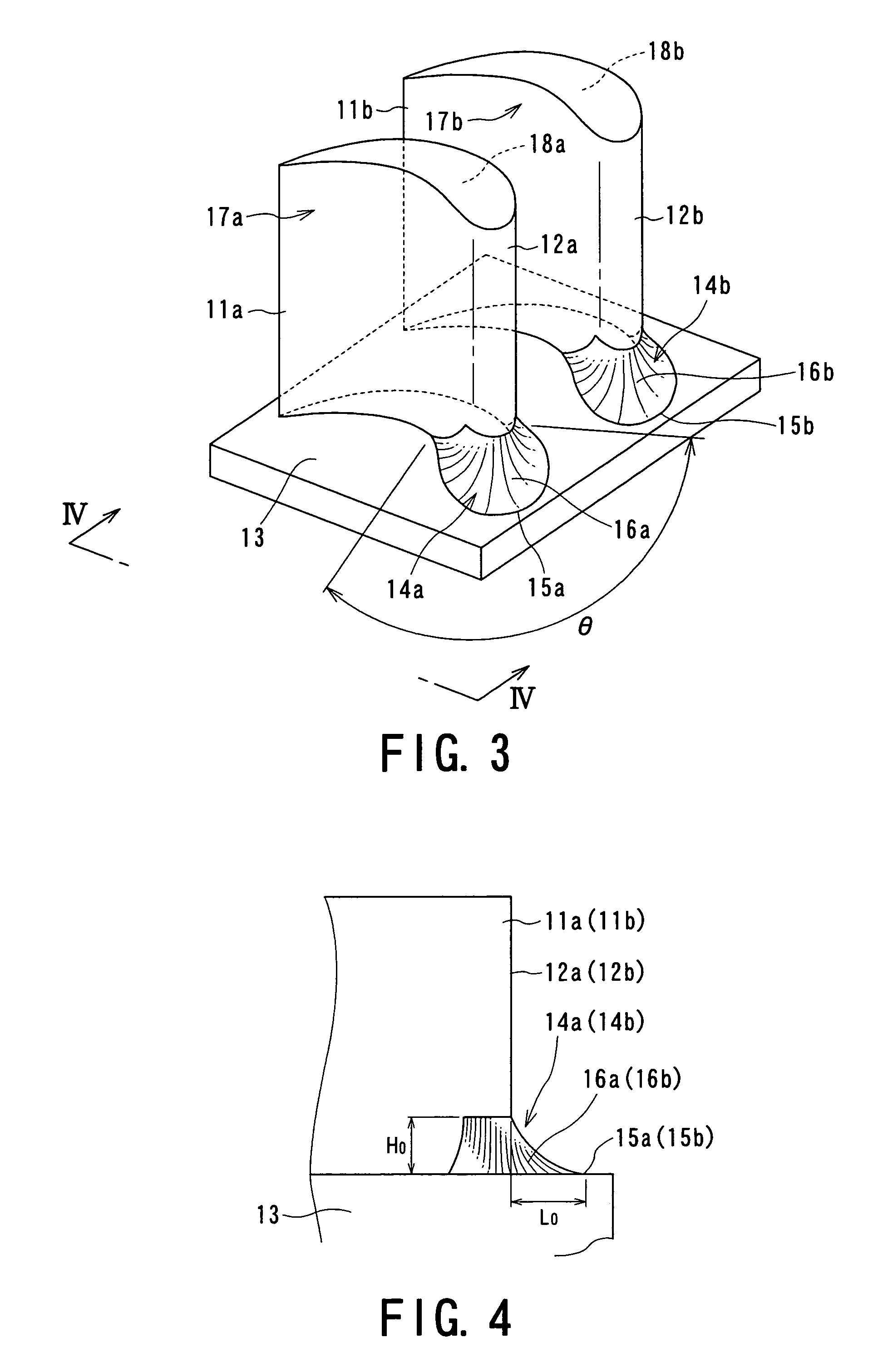
[0083]FIGS. 7 and 8 are conceptual views of a turbine blade cascade structure according to the present invention as an exemplary turbine rotor blade.

[0084]The elements of the embodiment which are the same as those of the first embodiment will be designated with the same reference numerals.

[0085]Likewise the first embodiment, in the turbine blade cascade structure of the embodiment, corner (root) portions defined by the wall surface 13 like a turbine disc and the front edges 12a and 12b of the adjacent blade bodies 11a and 11b provided on the wall surface 13 are provided with coatings 14a and 14b which extend therefrom toward the upstream side, and have cross sections formed as the protruded portions 16a and 16b each raised to the heights of the front edges 12a and 12b to form the concave curved surfaces. The wall surface 13 for supporting the blade bodies 11a and 11b includes a downward inclined surface 19 linearly angled to extend from an edge line of the front edges 12a and 12b to...


PUM


Abstract

A turbine blade cascade structure includes a plurality of blades arranged in series in a circumferential direction on a wall surface, in which a corner portion defined by the wall surface and a front edge portion of each of blade bodies supported by the wall surface, to which a working fluid flows, includes a cover portion (fillet) that extends toward an upstream side of a flow of the working fluid. The turbine blade cascade structure is capable of reducing the secondary flow loss of the secondary flow in spite of the fluctuation of an incident angle of the working fluid flowing to the front edge portion of the blade body.

Description

TECHNICAL FIELD[0001]The present invention relates to a turbine blade cascade structure, and more particularly, to a turbine blade cascade structure designed to reduce a secondary flow loss of a secondary flow of working fluid by making an improvement with respect to a root portion (blade root portion) and / or a tip portion (blade tip portion) of a blade body.BACKGROUND ART[0002]Recently, reinforcement of a blade cascade performance of an axial-flow fluid machine including a steam turbine, a gas turbine and the like has been required to be re-examined by reducing a secondary flow loss of a secondary flow of the working fluid, for example.[0003]The secondary flow loss of the secondary flow may cause great loss as serious as the profile loss defined by the configuration of the blade type.[0004]The secondary loss is considered to be caused by the mechanism to be described hereinafter.[0005]FIG. 27 is a conceptual view that explains the mechanism that causes the secondary flow, which is ...

Claims


Application Information

Patent Timeline
Patent Type & Authority Patents(United States)
IPC IPC(8): F01D5/14F01D9/04F01D9/02
CPCF01D9/041F01D5/145Y10S415/914Y10S416/02F01D5/143
Inventor MATSUDA, HISASHIINOMATA, ASAKOOTOMO, FUMIOKAWAGISHI, HIROYUKINOMURA, DAISUKE
Owner KK TOSHIBA
Why Eureka
Try Eureka